It's more important than ever to bring new designs to market that work reliably from the start. One way of ensuring a successful design is through rigorous testing of components, assemblies, and complete machines. However, extensive testing not only can delay bringing new designs to market, but having to build and modify prototypes can add substantial startup expenses. Computer simulation presents an alternative, but may not provide the extensive results of prototype testing. A cost-effective technique that combines the best of these is Hardware-in-the-Loop (HIL) simulation.
HIL analyzes hydraulic, mechanical, and control components of a design as real objects. These components become part of a simulation through interfaces. The computer simulation runs in real time and provides a complete system environment of the hardware under test. The hardware reacts and reflects the virtual effects of the real system.
Applications are based on a complete solution for HIL simulation, called IS Prototyping Duo. This solution allows convenient and efficient building of an HIL simulator, especially for controls connected to a physically oriented simulation model of the design. The IS Prototyping Duo provides a complete tool chain that starts with the physical model of the equipment over an offline simulation and ends by optimizing a real-time simulation in connection with the control system unit.
A real-world example
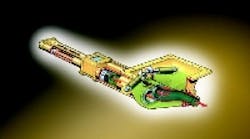
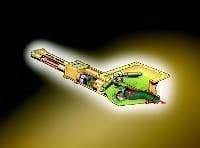
Hardware to be analyzed in a typical application consists of a computerized control unit for a concrete pump designed by Putzmeister AG. This control unit was connected to a virtual hydraulic-mechanical drive modeled in ITI-SIM for the HIL simulation. The core of the concrete pump drive consisted of two conveying tubes, each powered by an identical hydraulic cylinder, Figure 1.
The direction of cylinder pistons changes by reversing the flow direction of a pump in a closed hydraulic circuit. A computerized control unit gathers information about the piston displacement and the position of a switching tube. Furthermore, operation of the cylinders is monitored and is factored into the algorithm of control software.
HIL simulation environment
To conduct an HIL simulation, a user needs a hardware environment specifically adapted to the task. This environment computes the simulation model in real time and organizes communication between the control hardware and a real-time model.
The hardware environment used in this application consists of the following components, Figure 2:
- An application development system (Windows PC),
- ProSys-RT real-time computer (Linux PC), including measurement data processing, and
- a Putzmeister Simulation Box.
The Putzmeister Simulation Box incorporates the hardware of the electronic concrete pump control and electronic circuits for signal adaptation to a measurement data processing card. A standard PC with Linux operating system is used as the real-time platform — the ProSys-RT real-time computer.
A fast interface card organizes the data transfer between the real-time simulation model and the connected hardware. Administration of models and the model control is carried out on an application development system, which is a standard Windows-based PC. This PC generates the model for the hydraulic drive in ITI-SIM.
Hydraulic drive physical model
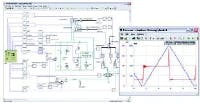
Starting with the hydraulic diagram, Figure 3, the drive in ITISIM is developed interactively using graphical tools. The simulation model contains different components from Mechanics and Hydraulics Libraries. The model is completed by objects from a General Objects Library for signal conditioning of input and output values. In addition, offline simulations can run with a sub-model describing the behavior of the real control.
Once the offline simulation is complete, the functionality of the ITI-SIM model is exported into C source code. The exported code can be used in a real-time environment by bundling it with a real-time solver and an input-output module. Before the export takes place, a code export assistant integrated in ITI-SIM defines which inputs, outputs, and other parameters are available as interfaces. The interface definition is supported by a user-friendly front end, which compiles and integrates all components for the hardware environment.
Real-time data exchange
The I/O-card of the ProSys-RT real time computer accomplishes the data transfer between the compiled simulation model and the hardware of the concrete pump control. The types of signals and their data formats can be different and are determined by the particular application. Signal preconditioning for time-critical signals can be accomplished on the RT card.
In this application, the control unit outputs PWM signals for solenoid valves. These output signals also serve as input signals of the real-time simulation model. To guarantee the real-time capability of the simulation model, the PWM signals are preconditioned so they can be measured by the RT-card. The RT-card processor then calculates the PWM rate and provides it as an input signal to the simulation model.
Input values of the concrete pump control become virtual sensor signals of the model computed in real time — for example, an analog signal representing the hydraulic cylinder supply pressure or a digital signal representing cylinder end stop position.
Observation and analysis
Input and output quantities defined in the code export can be observed and recorded during the HIL simulation. TCP/IP lets users observe signals live, as well as stimulating the system from outside via selected input quantities. Measurement values can be saved on the RT computer, which is especially important for time critical values. To do so, the user defines the measurement values, sampling rate, and data length. The data will be stored on the RT card and later transferred as one data packet to the processing computer for subsequent evaluation.
Parameters of the pump control can be changed and optimized from the results. Engineers find it especially important that the complete functionality of the real-time model (including non-linearities and fluid characteristics) is taken into account and implemented in the physical ITI-SIM models. In addition, engineers can determine critical system conditions through a virtual prototype.
Conclusion
Using Hardware-in-the-Loop with IS Prototyping Duo enables validating the performance of complex systems and their controls in early stages of development. ITI-SIM modeling and simulation software allows engineers to create, calculate, and optimize physical system models quickly and efficiently. The user-friendly interface to ProSys-RT allows a smooth transfer to HIL simulation in connection with electronic control units.
These all can reduce expenses incurred for cost-intensive tests and prototypes. All development stages are completely supported, including modeling, offline simulation, real-time code generation, and HIL simulation.
Carsten Obenaus and Uwe Grätz are Fluid Application Engineers at ITI GmbH, Dresden, Germany. For more information, visit www.itisim.com.
Software serves as circuit design assistant
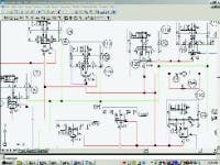
Screen image shows typical color-coded hydraulic schematic generated by HyDraw software.
Software that makes circuit design faster and easier has been around for more than a decade. In the fast-paced world of software, programs either evolve or disappear — as has been the case with several titles. One that has evolved is HyDraw software, developed by VEST Inc., Troy, Mich.
HyDraw is available for both Auto-CAD and Microsoft Visio platform. Both versions have similar features and functionality, although each exploits the strengths of the native platform. Circuit drawings created in Visio can be saved as DXF drawings. Similarly, AutoCAD symbols can easily be migrated to Visio.
Preloaded with libraries containing more than 4000 fluid power symbols, HyDraw allows users to create their own symbols and libraries. Familiar point-and-click menus enable easy insertion of symbols and model data into a drawing. Precision and accuracy of symbols and embedded data translate to significant productivity gains, and short project turn-around time.
Circuit connections are easily made using drafting utilities that allow connection lines to snap to and stay attached to symbols. Connector lines automatically add jumpers or connecting dots where appropriate. Master settings allow users to dictate visual properties of connectors — such as layer, font, and color — so drawings can be standardized to take on a corporate identity.
Networking benefits
The automation and utilities of Hy-Draw improve productivity, consistency, and reliability. Furthermore, it simplifies system proposal making and cost analysis — and is especially valuable for generating detailed parts lists. Design data from HyDraw can be imported into costing modules — 3-D CAD, manifold design software (MDTools, which the company also offers) and MRP and CAM programs — which makes the software versatile. The software is ideal for computer networks, so a company's system design data, model codes, pricing, and procedures all can be standardized.
The software is database-driven using Microsoft Access, allowing symbols and linked model codes, prices, and ratings of fluid power components to be stored and easily accessed for a project. Component manufacturers' catalog and service data can be linked to symbols, producing a consolidated design environment.
Symbols in HyDraw contain data-base-driven specifications, so parts lists can be created and extracted on demand. The extracted Parts List can be imported into AutoCAD, Excel, or into a company's MRP system, further strengthening the reliability of the Design to Order process. Alternative Bill-of-Materials formats can also be customized and stored.
Manifold port charts can also be created on demand. Automatic creation of these charts eliminates potential errors that can occur with traditional data entry. HyDraw can communicate connectivity and cavity information to downstream manifold design processes in AutoCAD and Autodesk Inventor. The digital, seamless communication to VEST's MDTools software results in completely error-free manifold designs.
The AutoCAD-based version is intended for the serious design engineer who wants to draw precise, detailed circuits, quickly, and reliably. Applications engineers who do not wish to deal with the complexity or expense of an AutoCAD platform generally opt for the Visio version of HyDraw.
Hydraulic system designers, sales and application engineers, and manifold designers use HyDraw to quickly and easily create error free circuit designs.
For more information, contact VEST Inc. at (248) 649-9550, or visit www.vestusa.com
More information is available by e-mailing [email protected] or by visiting www.iti.de


