Versatility is one of the biggest advantages of hydraulics. It’s equally at home producing rotational motion as it is generating linear motion. Furthermore, today’s electrohydraulic controls make it a cinch to precisely control force, torque, speed direction, or any other dynamic parameter. Therefore, once a hydraulic drive has been specified for a machine, it only makes sense to tap into that hydraulic system for multiple functionality.
However, there’s a practical limit to the number and types of functions that should be served by a single pump. In some cases, you can add a second pump to the back of a primary pump — commonly called tandem, stack, or piggyback mounting. But tandem mounting generally is only practical when the secondary pump is substantially smaller than the primary one. So when you need to drive two or more pumps from a single internal combustion engine, a pump drive box presents an effective solution.
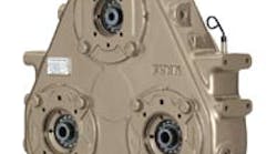
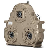
A pump drive is attached to the flywheel end of an engine and drives a hydraulic pump or pumps. A modular pump drive encompasses multiple mounting points for attaching hydraulic pumps. It’s what makes an engine versatile because you have one power source. And with a pump drive — or multiple pump drives — you can split that power to run to many different locations.
To stack or not to stack
A common method for routing hydraulic power to multiple locations with multiple pumps is to use a single-output pump drive and stack multiple hydraulic pumps together. But before deciding to tandem mount multiple pumps, you should ask:
• Will the components that need to be powered be working simultaneously? If so, can the engine provide the required torque?
• Does the vehicle impose any space constraints that would preclude stacking pump drives?
When one pump is stacked behind another, all the power for the pump stack in total must be transmitted through the primary pump input shaft. Often that shaft lacks the torque capacity to drive all pumps simultaneously. Another limitation comes from the vehicle, which sometimes doesn’t have the length available to stack the pumps. Also, Tier 3 and Interim Tier 4 emissions-certified engines are introducing some restraints on the available room in the engine compartment. This means some creativity and flexibility in the packaging of components is sometimes needed.
Whether or not it’s feasible to stack pumps on a single pump drive output usually depends on the torque capacity of the primary pump’s splined input shaft. Splined shafts are usually sized specifically for a single pump, and the load is increased when additional pumps are tandem mounted to the primary pump. If those pumps will never be energized at the same time as the primary pump, then there’s no issue. But if two or more stacked pumps come on simultaneously, then there’s probably not enough capacity in that primary shaft to transmit power to both secondary pumps. In any case, the benefits of a modular pump drive should now become apparent.
Modular pump drives
A modular pump drive approach provides thousands of choices for gear ratios, pump adapters, and mounting options. With so many combinations, most machine manufacturers can find a pump drive that meets the configuration and reliability needs of its applications.
For example, John Deere’s Funk brand of pump drives come in 5000 variations when you consider the number of models, each one of which can have five or six different spline configurations and use an SAE A, B, C, or D output pad. Also, each of these configurations can be driven through a planetary gear drive, by a flange or shaft power takeoff (PTO) input, or it can have a clutch in front of it. These configurations are just for the pump drives and do not even take pump features into account.
However, the modular drive does not necessarily have to power a hydraulic pump. An alternative approach is to use one or more of the drive’s outputs as a mechanical PTO. Some equipment builders use one pump drive to power another using the drive shaft of the first pump drive. Some of Deere’s pump drives have PTO outputs available to power another pump drive, or that PTO could power other equipment directly, such as an air compressor or generator.
The flexibility of a modular pump drive allows equipment manufacturers to match pump drive speed to the optimum operating speed of an engine to achieve the maximum performance and fuel economy.
The flexibility of a modular pump drive also lends itself well to hybrid drivetrain systems because modular pump drives are efficient at routing and using all of an engine’s power.
Selection by torque
The most reliable technique for selecting a pump drive is the torque method. Suggested here is a step-by-step procedure:
1. Determine the net peak torque (lb-ft or N-m) transmitted from the engine. This will serve as the maximum input torque to the pump drive. Remember to deduct any continuous parasitic losses.
2. Determine the maximum input torque (again, in lb-ft or N-m) required to drive each and every hydraulic pump attached to the pump drive. If a pump will be driven at a speed other than the engine’s flywheel speed, be sure to consider the drive ratio in your calculations. A drive ratio other than 1:1 may be chosen so the engine can run at a speed for optimum fuel economy — say, 1800 to 2200 rpm — while the pumps may run most effectively at, say 2200 to 2700 rpm.
3. Using the lesser of the torque values calculated above, select a pump drive series with a maximum input torque capacity that exceeds the torque requirements of the pumps.
Sometimes you can take a shortcut. If the engine’s peak torque is less than the pump drive’s peak input torque, you don’t need to go any further because the engine cannot overpower the pump drive. A smaller pump drive could be used if the engine’s peak torque rating isn’t oversized to increase reliability. Additionally, the torque rating might be oversized because the engine is also driving some other equipment. If that’s the case, you can proceed to step two.
Step two helps determine the sum of the load of all the hydraulic pumps that will be mounted to the pump drive, whether it’s one pump or nine pumps. If the sum of the load required from all the pumps is lower than the engine peak load, then that’s the torque needed to size the pump drive.
For example, say an engine’s net peak torque is 825 lb-ft and has the following requirements:
• torque required at Pump A is 225 lb-ft,
• torque required at Pump B is 250 lb-ft,
• torque required at Pump C is 143 lb-ft, and
• the engine will run at 2000 rpm while the pumps will be driven at 2390 rpm.
This means the sum of all pump torques is 618 lb-ft, and the pump drive ratio is 0.836:1 (speed increase). Dividing 618 by 0.836 indicates that the effective input shaft torque required is 739.2 lb-ft, meaning a pump drive with a torque capacity above 740 lb-ft is needed.
Selection by power
An alternate technique for selecting a pump drive is called the power method, but this should be used only if the torque is unknown.
1. Determine the net peak power (hp or kW) transmitted to the pump drive from the prime mover.
2. Determine the equivalent power (hp or kW) by multiplying the net peak power by the appropriate service factor for the application. Take into account the engine output characteristics, as well as the equipment’s expected daily hours of use.
3. Using the equivalent power, select the proper pump drive series with a maximum input power capacity that exceeds the equivalent power of the hydraulic pumps.
Both methods require the following additional steps for determining the proper pump drive configuration:
A. Determine the number of pump pads required by making a selection from the models available within the pump drive series. Be sure to take into consideration the maximum output torque rating per pad, and the center distance between the mounting pads for clearance of the pumps and their hydraulic plumbing.
B. Select a gear ratio from the options available for the selected model that will provide the desired pump speed and flow. Be sure to consider the maximum recommended speed for both the pump drive series and the hydraulic pumps being used.
C. Select the desired input configuration from the available options for the pump drive series:
• engine mounted — drive plate or torsional coupling driven,
• engine mounted — clutch-driven (consider clutch limiting speeds and torque capacity), or
• remote mounted. D. Select the desired output configurations from the available options for the pump drive series:
• pump adapter plates,
• Pump shaft adapter sleeves (if required), and
• drive shaft or PTO options.
The manufacturer of the pump drive box can assist in determining whether the configuration will meet an application’s requirements, including expected durability for the specified duty cycle. Most manufacturers will be able to assemble the initial package and modify it as necessary if requirements change.
Additional considerations
The presence of unwanted torsional resonant frequencies in the system can quickly cause damage to components in the drivetrain and reduce the life of the components. The engine manufacturer, torsional coupling supplier, or an independent consultant can perform torsional vibration analysis.
Also ensure that a service and support network is in place when specifying a pump drive. The benefits of a modular assembly system and an experienced regional distribution network can be instrumental in keeping equipment up and running.
Getting the most out of your equipment often depends on close integration between all components. A company that manufactures and integrates all the diverse components of a drivetrain provides the experience to help you select the best pump drive for the application.
For more information, contact the author via e-mail at [email protected]


