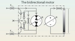
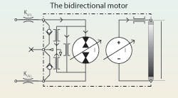
In concluding the discussion from last month, motors are somewhat more sensitive to problems with the case drain than are pumps. This is because motors, more often than not, are required to reverse direction during operation. Figure 3 shows the powered and return lands of a directional control valve in a motor circuit. The return land, depending upon its K value, will restrict return flow and cause pressure in its associated motor port to always be higher than the tank pressure. Motor reversals, of course, require input flow to be reversed, so the ports will alternate between high and low pressure. Valves for controlling direction and speed, therefore, cause even the low pressure side of the motor to experience pressures that approach half of the supply pressure. Actual pressure depends on the valve’s coefficient value, KVRL, the load, the application, and the means of control. The case drain becomes more critical if reversing is required.
The differences with pumps
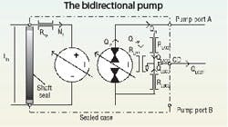
The analytical schematic for the pump can be helpful for visualizing issues with the case drain, just as was the case with the motor. Figure 4 shows a Type 2 analytical schematic of the most general configuration for a pump. It is, in effect, a mirror image of the motor. Two mechanical ports represent the hydraulic analogy of the input shaft, and three hydraulic ports. It is necessary in applications where the pump’s A and B ports must operate alternately at high and low pressures. Most pumps do not operate that way.
Most hydraulic pumps operate with a single direction of rotation — they operate with one power port connected to tank and the other to the high pressure elements to be powered. In addition, most variable displacement pumps do not operate, nor are allowed to operate, over center. That is, they do not have to reverse direction of output flow.
In these unidirectional applications, the case drain need only be connected to the pump inlet side. This ensures that the case is always at low pressure, so the shaft seal can be low pressure type and the case need not be designed as a high pressure-containing envelope. The analytical schematic of the unidirectional output pump with external case drain connection is shown in Figure 5, although some pumps are designed with an internal connection.
The above connection allows the pump to be characterized as a Type 1 model. The reason is because with the connection as shown, RLBCD experiences no differential pressure. Therefore, it contributes nothing to the case drain leakage. Also, with the connection as shown, all the case drain leakage is recirculated and is indistinguishable from the port-to-port leakage inside the pump. If the case is drained with external plumbing, then the case drain component of flow can be measured, and RLACD can be determined. On the other hand, if the connection is internal, all the leakage is lumped into RLPP.
The next installment of “Motion Control” will explore applications in which both the pump and motor are reversible. The subject will deal with the hydrostatic transmission (HST) and will show how the Type 2 analytical schematic demonstrates the need for the peripheral equipment to make the HST practical and fully functional.
Click here to view the next article in this series: Understanding Hydrostatic Transmissions.
Handbook serves electrohydraulic system designers
The newly published fourth edition of the Designers’ Handbook for Electrohydraulic Servo and Proportional Systems contains even more useful information than its predecessor, the highly successful third edition, which has become the defacto Bible for electrohydraulics technology.
Now you can learn even more about electrohydraulic systems and their design, including:
• how to calculate and control pressure losses in plumbing, subplates, and manifolds,
• how to analyze and control a variety of mechanical loads, including conveyors and belts and triangulated loads,
• valve dynamic properties and how to include them in your system,
• electronics, especially transducers and signal conditioning, and
• mobile equipment electrical systems, including batteries and charging systems.
There is no limit as to how electrohydraulics is going to revolutionize our industry, so order your copy to secure your career in this dynamic technology. And if certification in electrohydraulics is your goal, the fourth edition of the Designers’ Handbook is essential to your preparation. Don’t risk being left behind in a world where the only constant is rapid change.
To order, visit our Bookstore. Print the PDF order form, fill it out, and mail, fax, or e-mail it to us.
