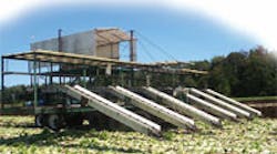
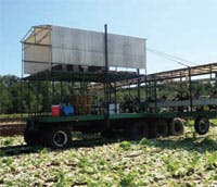
As with most harvesting equipment, lettuce harvesters move slowly in the field to ensure maximum yield and to prevent damaging the crop. However, once a row has been harvested, the machine must quickly be repositioned to begin harvesting the next row for high productivity. Furthermore, lettuce often grows in multiple fields, so the harvester must also be able to quickly move from one field to another.
Another challenge for lettuce harvesters is traction. Fields are often muddy because growing lettuce requires using a lot of water, so even a four-wheel-drive vehicle can get bogged down. A track drive would offer maximum traction, but would cause too much damage to the field. As it turns out, six-wheel drive provides enough support to keep the vehicle from getting bogged down in mud and also reduces ground pressure compared to four-wheel drive. It also provides enough traction to keep the vehicle moving — even if wheels become caked with mud.
So the challenge is to provide a drive that can distribute power to six wheels, provide low-speed, high-torque power for harvesting, and high-speed drive for moving from one location to another. All of these requirements can easily be met with a hydrostatic transmission. However, an unconventional lettuce harvester uses a patented circuit to provide low-speed, high-torque or high-speed, low-torque operation simply by shifting a valve.
Power and versatility
As with most agricultural equipment, the lettuce harvester uses hydraulics for more than just propulsion. It also features hydraulic steering, braking, positioning of implements, and it also drives conveyors. However, the most unusual aspect of the lettuce harvester is its hydrostatic drive system, which consists of a variable-displacement, axial-piston pump with reverse-flow capability from Sauer Danfoss, Ames, Iowa.
Each of the harvester’s six wheels is driven through a 30:1 planetary gear wheel drive from Auburn Gear by a Sauer Danfoss Model OMS motor sized at 12 in.³/rev. The pump, capable of 50 gpm at 4500 psig, was chosen for its combination of high performance and reliability at a reasonable cost.
The harvester gives the operator a choice of two speed ranges — the low-speed, high-torque mode provides harvesting speed of 300 ft/hr (5 ft/min) and a high-speed, low-torque mode for speeds to 4 mph. Had the harvester required only a 2:1 range, it could have been fitted with a regenerative circuit that uses one 4-outlet flow divider.
For a description of this circuit, refer to the December 2007 issue of Hydraulics & Pneumatics, or view the article by clicking here.
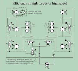
But what makes the harvester achieve its efficient and effective high-torque drive is innovative hydraulic circuitry that switches the wheel drive motors between parallel flow (low-speed, high-torque mode) and series flow (high-speed, low-torque mode). This is accomplished using a pair of directional control valves and two rotary flow dividers, as shown in the schematic. This patent-pending design belongs to HyVee Equipment LLC, Clarksville, Tenn.
Achieving the improbable
The schematic shows a simplified view of the harvester’s hydraulic system. It is shown in its zero-state, at-rest mode. In this mode, the pump is at zero displacement, but once the pump’s displacement control moves off center, the vehicle will be in its low-speed, high torque mode.
In the low-speed forward mode, fluid flows from the left side of the bidirectional pump to junction 1, between valves BL and BR. Line pressure is also transmitted to solenoid valve A. However, because valve A is closed, pilot pressure is not transmitted to any downstream components.
From the junction, fluid flows to valves BL and BR. But because neither valve receives pilot pressure from valve A, they remain in their de-energized state, so they route fluid up to their respective rotary flow divider. Each of the two flow dividers is a Rotary Drive Roller Stator design from White Drive Products.
Flow divider circuits are not limited to mobile applications; similar circuits using flow dividers could also be applied to hydraulic conveyor drives. The flow dividers would ensure that each conveyor motor runs at the same speed, and each conveyor would run efficiently whether lightly loaded or fully loaded.
Each flow divider in the harvester is essentially three hydraulic motors with a common shaft. So fluid entering the flow divider assembly flows into all three motors and turns the common shaft, which causes all three to rotate at exactly the same speed. Therefore, flow from each of the three outlet ports of the flow divider is 13 that of the flow entering the single inlet port. This establishes the flow divider as a meter-in device to all three wheel motors.
From the flow divider, an equal amount of fluid flows into each wheel motor, so each rotates at the same speed. The flow dividers ensure that each motor receives 16 of pump flow — half of pump flow goes through valve BL, half goes through BR, and each flow divider sends 13 of the flow it receives (half of total flow) to each wheel motor.
Theoretically, though, each wheel motor has full pump pressure available, so it is capable of high torque. Fluid exiting each motor flows back to the pump either directly or through valve BM. This establishes a parallel flow circuit for each of the two sets of motors.
Switching modes
To switch the harvester into its high-speed, low-torque mode, the operator activates a switch that energizes the solenoid of valve A. The solenoid opens valve A, so pilot pressure now is transmitted to valves BL, BR, and each motor valve BM With valves BL and BR shifted, fluid now flows directly to the bottom motors in the schematic. However, because valve BM receives pilot pressure, it has shifted, so fluid no longer flows back to the hydrostatic pump. Instead, fluid flows from the bottom motors to the middle ones. Likewise, fluid exiting the middle motors flows into the top ones. Finally, fluid leaving the top motors returns to the pump.
This single flow stream through each pair of three motors establishes a series motor circuit. Each motor receives half of pump flow from valve BL or BR, which provides high-speed capability. Pressure capability, however, is now shared by three motors on either side of the machine. So the motors operate in a high-speed, low-torque mode.
Reversing the order
Switching the harvester into reverse is accomplished through the pump’s displacement control. For reverse operation, the pump’s swashplate moves over center, so fluid flows from the right side of the pump, as shown in the illustration.
Hydraulic flow in the reverse mode again can be seen in the schematic. If valve A is not energized, pilot pressure is not transmitted to valves BL, BR, and BM. Fluid flows from the right side of the pump to junction 2. Flow splits at this junction and travels around to the three motors on the left and three on the right. Fluid flows into the two lower motors through their respective valve BM and directly into the upper motors. Exiting the motors, fluid then flows into the respective flow divider.
Fluid from the lower motors cannot flow through valve BL or BR because they are closed, by virtue of no pilot pressure. From the flow divider, fluid combines at junction 1 and flows to the left side of the pump. In this configuration, each flow divider acts as a meter-out device — again ensuring that all three motors rotate at the same speed.
When the harvester is in the high-speed, low-torque mode in reverse, the operator activates the lever for high-speed operation, so valve A opens to route pilot pressure to valves BL, BR, and BM. The pilot pressure shifts the valves, so fluid can no longer flow through all six motors in parallel. Instead, fluid flows past the bottom and middle motors and enters the top motors. From there, fluid flows into the middle motors through valve BM, then to the bottom motors through their respective valve BM.
After exiting the bottom motors, fluid cannot flow into the flow dividers because valves BL and BR, have shifted to block flow from them. Instead, fluid exits the bottom motors and flows through valves BL and BR, and, finally, into the left side of the pump.
Design considerations
As with any system design, decisions had to be made based on reliability, performance, efficiency, cost, and practicality. For example, all valves could be solenoid operated instead of pilot operated. However, designers deemed pilot-operated valves more reliable for this application. Pilot actuated valves are more tolerant of fluid contamination than solenoid valves are, and electrical actuation is sensitive to corrosion and malfunctions from contact with water. Pilot lines are also less likely to be damaged from unpredictable environmental conditions.
Another consideration was the choice for valves BL and BR. A larger, single valve could have been used. However, designers found smaller valves to be more readily available — which would be important if a replacement was needed — and also less costly. Moreover, by using two smaller valves, the BL and BR valves are the same as the BM valves. This simplifies inventory and eases maintenance by consolidating part numbers.
The flow dividers also required careful consideration. The first choice was between rotary and valve-type flow dividers. However, because they split flow mechanically instead of using energy-wasting orifices, rotary flow dividers are much more energy efficient than their valve-type counterparts, so rotary flow dividers were chosen.
Another consideration was the number of flow dividers to use. Designers quickly settled on two 3-outlet flow dividers based on cost, practicality, and because the two flow-divider system provides a split power train, which operators and technicians would be familiar with.
Because speed, direction, and driving mode all lend themselves to electrohydraulic control, the harvester could have been fitted with a multi-axis joystick for single-point control. However, designers wanted to use conventional type controls. Therefore, speed is controlled with a foot pedal coupled with an electronic transducer that sends a signal to the pump’s displacement control. So as the operator presses farther on the accelerator pedal, pump displacement increases, which increases vehicle speed.
Forward and reverse is controlled through a lever similar to that used in conventional transmissions. Pivoting the lever to the reverse position changes the polarity of the signal from the accelerator pedal transducer. So pushing on the pedal increases speed in the reverse direction.
The harvester is also shifted out of and into low-speed, high-torque using a lever-activated switch. This switch is normally open (de-energized), so it does not send a signal to solenoid valve A unless the operator moves the lever into the high-speed mode. An interlock is also provided to prevent the vehicle from starting while in the high-speed mode.
Mark Perry is with Fitzsimmons Hydraulics, Clarence, N. Y., and George Morgan, P. E., is a registered patent agent with Morgan & Associates, Evansville, Ind. For more information on the lettuce harvester, e-mail [email protected]. For more information on the patent-pending flow divider circuit, e-mail George Morgan, P. E., at [email protected].
