Pressure transducers, when connected to an appropriate electrical source and exposed to a pressure source, will produce an electrical output signal (voltage, current, or frequency) proportional to the pressure. Most transducers are designed to produce output that is linear with the applied pressure and independent of other system variables — the most important of these being temperature. Most outputs are in millivolts, volts, milliamperes, and, sometimes, kilohertz.
Pressure transducers have a sensing element of constant area and respond to force applied to this area by the fluid pressure. This force deflects a diaphragm, bellows, or bourdon tube. In turn, these deflections, strains, or tensions are converted to electrical outputs through any of a variety of different transduction methods.
Electrical input/output
To operate, most pressure transducers require an electrical input (usually called excitation). Many operate from a 5- to 10-V dcinput and produce full-scale outputs from, say, 0 to 20 mV and 0 to 100 mV. Transducers that produce high level voltage outputs operate from voltage sources. Typical outputs are 0- to 5-, 1- to 5-, 1-to 6-, and 1- to 11-V dc. Digital control circuits can be interfaced by routing transducer output through an analog-to-digital (A/D) converter or by using a transducer with a frequency output. This allows pressure to be monitored by microprocessors, programmable controllers, computers, and similar electronic instruments.
Pressure transducers that generate a current output usually are called transmitters. By definition, they are variable-current devices and produce 4- to 20-mA outputs with supplies of widely varying voltage.
Outputs are chosen with the following factors in mind:
- the type of device that will receive the transducer's output signal (programmable controller, panel meter, signal conditioner, etc.)
- the distance between the transducer and its receiving device
- presence of electromagnetic interference (EMI) in the environment, which can come from sources such as power lines, welding equipment, solenoid valves, motors, 2-way radios, etc., and
- cost as it relates to the entire installed system (not just the transducer).
Measurement error
Pressure transducers are mechanical structures made from more than one material. Because of this, they respond not only to changes in pressure, but to changes in temperatures as well. These changes can affect both the zero and full scale output (FSO) of the transducer, regardless of its type. The term "temperature effect upon zero" refers to the change in output at constant pressure as temperature is varied over a stated range. Extreme temperature fluctuations may change a transducer's output signal even though pressure remains constant.
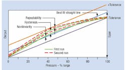
Many other characteristics — such as linearity, hysteresis, repeatability, etc. — help to determine the measurement accuracy of a pressure transducer, Figure 1. Additional factors, equally important, are more elusive. These include packaging, configuration, construction materials, and internal design. Each of these can be appraised on the basis of field testing and/or experience.
Overall, the best pressure transducer for one application is not necessarily the best for another. In fact, a transducer with the second best performance may be the best choice for an application if its price is significantly lower.
Pressure spikes
Pressure spikes are microsecond to millisecond bursts of pressure that can reach 15 times the normal system operating pressure. For example, if a valve shifts abruptly to block flow, a shock wave can be generated within the system. Likewise, if a hydraulic system is moving a load and the load suddenly stops, the system may react with a brief surge of pressure.
System control electronics — such as PLCs with millisecond scan times — are not fast enough to detect spikes of such short duration. Often, the first indication that a system is generating pressure spikes is a positive shift in a pressure transducer's zero output. System control electronics commonly indicate the shift in transducer output as a pressure out-of-range condition, which could cause the system controller to shut down.
Pressure transducers are the components most vulnerable to damage from pressure spikes. Transducers, which have much quicker response times, react to spikes and show signs of having been over-pressurized. This is not because the transducer is less durable than the mechanical gage it replaced. In fact, a transducer designed for severe service should have been specified. Spikes also damage the machines that generate them. The erratic flow of liquid, common in systems that generate spikes, reduces efficiency and accelerates wear on valve ports and seals.
Pressure spikes usually can be detected with an oscilloscope through a transducer of, say, five times the normal operating pressure range. Once it is determined that spikes exist in a system, any of several practices can be used to prevent them from damaging the transducer. A transducer with a higher pressure rating can be used. However, doing so sacrifices accuracy in the normal operating range because a transducer with a wider operating range has poorer resolution.
As an alternative, a snubber can be used to dampen the spike. A snubber is an orifice installed in piping between the transducer and the source of the spike. A potential disadvantage of this practice is that it slows the response of the measurement. If neither measurement resolution nor response can be compromised, a transducer that can tolerate spikes should be specified. Obviously, these transducers cost more.
Importance of temperature
Temperature is a major consideration in the performance of pressure transducers. As temperatures change, different materials expand or contract at different rates, which creates residual stresses within the structure. These stresses can change the output of the transducer by changing its geometry, mechanical properties, and electrical characteristics. While manufacturers take great care in selecting materials and determining how they are put together, these changes are inevitable. Transducer manufacturers compensate for these changes in a variety of ways — generally, by electrically adjusting the transducer's output circuit.
Transducers are specified to have a compensated temperature range. Within this range, the transducer will perform within published specifications. Transducers also have an operating temperature range. Transducers will continue to perform within this range, but an operating error likely would exceed published specifications. For example, a transducer's typical compensated range might be 30° to 130° F, while its typical operating range could as great as –60° to 200°F.
The degree of compensation is expressed by two specifications: Thermal effect on zero gives the boundaries within which the zero value of the transducer is compensated to stay. This is usually published as 5x% of FSO within the compensated range. Some transducer manufacturers may publish the same value as 5x% of FSO/°F within the compensated range; this makes the numbers look smaller.
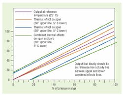
Thermal effect on span gives the boundaries within which the full scale output of the transducer is compensated to stay. This is usually expressed as 5x% of reading within the compensated range. Here, too, some manufacturers may publish the same value as 5x% of reading/°F within the compensated range. Graphically, the thermal effect on span can be expressed as shown in Figure 2.
Thermal errors are separate from other errors affecting total transducer accuracy (linearity, repeatability, and hysteresis). These errors must be accounted for and specified separately. Accuracy over the compensated temperature range must include the thermal effects on zero and FSO.
It is important to realize that performance specifications of transducer manufacturers refer to ambient temperature — the temperature of the air surrounding the external case of the transducer. Users also must be aware of media (fluid) temperature, because it can have a significant effect on the actual operating temperature of the transducer and, therefore, its performance.
Electromagnetic interference
Electromagnetic Interference (EMI) can affect transducer performance. High field strengths tend to affect transducer outputs. In some cases, these fields can completely saturate internal amplifiers to the point where erroneous outputs are produced regardless of the pressure input.
There are shielding and grounding techniques that are remedies for the effects of EMI. Also, wires should be carefully routed from the transducer to its receiving device so as to avoid EMI areas. Solutions are specific to each problem presented.
Only a few transducer manufacturers specify EMI protection. This is stated as: percentage of full scale error divided by a frequency range up to a maximum field strength. Example: Full scale output error typically is less than 1% over the frequency range of 20 kHz to 2 GHz at field strengths up to 100V/m. While these specifications are difficult to relate to the real world, the fact that manufacturers supply EMI data in their specifications indicates they have had some experience dealing with this interference.
Summary
An ideal transducer for one application could be unsatisfactory for another. With the wide variety of transducer products to choose from, knowing what features to look for and how to interpret specifications for a particular application will help you choose transducers with confidence.
One transducer may cost five or ten times more than another, but offer comparable performance characteristics. This cost difference can usually be attributed to additional capabilities built into the more expensive transducer. Immunity to electrical noise or the ability to sustain pressure spikes are two characteristics that add cost to a transducer without improving basic performance parameters. However, specifying a transducer without these characteristics, in an application clearly needing them, ultimately will result in an unsuccessful application.
Furthermore, the more expensive transducer may actually cost less when considering economics of an entire system. The less expensive transducer may require additional components that make it function in an otherwise unacceptable environment.
In general, as the number of capabilities increases, so does cost of the transducer. Some characteristics substantially add to a transducer's cost while others do not. It is important to evaluate each application to decide what characteristics are absolutely essential to an application and which are desirable, yet cost effective.


