Question: I put together a positioning system to help form pie crusts in a mass production operation. At times the system breaks into noisy and even violent vibration and oscillation. Why does that happen and how does one make it stop?
Answer: There are many reasons why feedback control systems break into sustained oscillations, a condition referred to generically as “instability.” Stability issues have been the bane of control system engineers since the earliest days of steam engine speed governors. But even today’s computers have not given us a universal solution.
A common cause of instability is excessive loop gain. It is corrected by reducing the gain of the servo or proportional amplifier, but systems with low hydromechanical resonant frequency can become sluggish and/or springy in a way that is unacceptable. Other frequency-dependent compensation methods are needed in such cases but are too complex to go into here except to say that other system variables need to be measured and fed back. A motion controller may have built-in features to provide such compensation.
Instability can occur whenever integral control is used in a feedback system with excessive hysteresis. Stiction can sometimes cause instability, especially when integral control is used. And overcompensation of deadband compensators can induce continued, limit cycle oscillations. The challenge of the systems integrator is to identify the cause of the instability so it can be corrected.
Question: What does the term step response mean and how do I interpret it relative to a valve?
Answer: Step response testing is a means of determining how fast a valve responds to a sudden change in input signal. To do a step response test, the output of the device — a valve — is measured and recorded on a continuous recording device after a switch is closed on the input, and we look at the output trace to see how fast it responds. It is an alternative to the frequency response test, because there is a correlation between the two. That is, the valve with the highest frequency response will also have the shortest step response time. There is a very old approximation that servo jocks have used for decades: The time response to a step command is approximately the reciprocal of the valve’s 90° phase shift frequency.
Question: What is bandwidth?
Answer: Technically, bandwidth applies to that band of frequencies that will pass through a band pass filter. However, it has come to be used to mean the highest frequency that a system will pass. It is used synonymously with frequency response. I certainly use it that way. So, if we have a valve with a 90° phase lag frequency of 50 Hz, we say its frequency response is 50 hz. We also say its bandwidth is 50 hz.
Question: What are ramp controls?
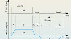
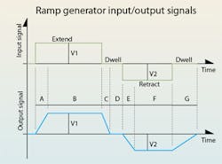
Answer: The ramp control is a special purpose signal conditioner that provides rudimentary, but effective, acceleration control. For example, imagine a machine axis powered by a hydraulic cylinder controlled by a proportional joystick. If the operator suddenly shifts the joystick to extend, retract, or stop the cylinder (the upper plot in the illustration), the axis will, with equal suddenness, accelerate — perhaps even causing damage.
The ramp control would be placed between the joystick output and the proportional valve’s input. When the ramp generator circuit receives a sudden (step) command, it does not simply amplify the signal and send it on. Instead, the output gradually rises or falls (ramps) to reach the input (the lower plot in the illustration), and, thus, gradually shifts the proportional valve to gradually accelerate the cylinder. It provides smooth starts and stops. User adjustments are available to control the ramp time on and ramp time off, and normally in both directions of hydraulic actuator motion.
Question: What is a motion controller? Do I need one to use a servo or proportional valve?
Answer: First of all, motion controllers can be used on either servo or proportional valves. A motion controller is the name given to a special purpose digital computer that is dedicated to the control of industrial machinery. The same motion controllers used on electrohydraulic equipment can be used on other kinds of actuation devices, such as electric servomotors. However, the practitioner of the electrohydraulic art is well-advised to use motion controller suppliers with specific hydraulic experience.
The motion controller has data logging and recording devices that receive signals from transducers and sensors. Included input interfaces accept analog voltage and current signals. They are called analog-to-digital converters (ADC, or A/D converters) and motion controllers usually have several A/D converters (channels) so that multiple analog inputs can be accepted. Other capabilities accept digital signals from encoders for positional control. Output interfaces include digital-to-analog converters (DAC or D/A converters) for driving servo and proportional valve driver amplifiers. The controllers might also have the ability to output PWM signals.
The most important part of the controller is its computational ability. It allows the user to formulate endless variations on control algorithms, including such things as deadband compensation for proportional valves. The second most important part of the motion controller is that it outputs so-called motion profiles. They are programmed motion commands that dictate where the output actuator should be every single millisecond of its life. This provides true “cradle-to-grave” control.
Question: What is a buffer?
Answer: A buffer is an electronic device that isolates one device from another. An amplifier is a form of buffer. The simple explanation is that what changes on the input is immediately felt at the output, but what changes on the output is not felt on the input. Your car provides an analogous situation. If you step on the gas your car accelerates. But if you encounter a hill, you do not feel it in your foot. The engine feels it, and you may think you feel it in your foot as the engine strains to make a steep grade, but that’s all psychological. The engine, in its function as an amplifier, “buffers” your foot and leg from the strains of the engine and the hill.
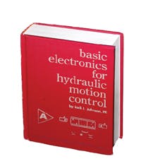
Basic Electronics for Hydraulic Motion Control
This is where your basic electronic training starts. This book, unlike many others, is written specifically by a practitioner of the hydraulic art for engineers and technicians working in hydraulics, but it teaches you all you ever needed to know about electronics. Your personal understanding of hydraulics is your ticket to learning electronics with this book, which is filled with analogies to simplify the understanding of concepts.
Everything you wondered about and need is here: transducers, interfaces, signal conditioners, pulse width modulation, controllers, amplifiers, transistors, analog electronics, digital electronics, and much, much more. It is a must read and reference for anyone interested in certification in the exploding technology of electrohydraulics.
It uses your knowledge of fluid power to help you learn and understand electronics. Order your copy now and get the book that makes electronics fun and easy to learn.
Authored by Jack L. Johnson, P.E., edited by Hydraulics & Pneumatics, and published by Penton Media, the hard cover textbook (ISBN 0-932905-07-2)contains 438 pages and sells for $49.95, plus shipping and sales tax. To order, or for more information, visit the Bookstore and download the order form.


