*Editor's Note: This article was updated in February 2024.
Evacuating air from a closed volume develops a pressure differential between the volume and the surrounding atmosphere. If this closed volume is bound by the surface of a vacuum cup and a workpiece, atmospheric pressure will press the two objects together. The amount of holding force depends on the surface area shared by the two objects and the vacuum level. In an industrial vacuum system, a vacuum pump or generator removes air from a system to create a pressure differential.
Because it is virtually impossible to remove all the air molecules from a container, a perfect vacuum cannot be achieved. Of course, as more air is removed, the pressure differential increases, and the potential vacuum force becomes greater.
Pressure Units Used to Determine Vacuum Level
The vacuum level is determined by the pressure differential between the evacuated volume and the surrounding atmosphere. Several units of measure can be used. Most refer to the height of a column of mercury — usually inches of mercury (in.-Hg) or millimeters of mercury (mm-Hg). The common metric unit for vacuum measurement is the millibar, or mbar.
Other pressure units sometimes used to express vacuum include the interrelated units of atmospheres, torr, and microns. One standard atmosphere equals 14.7 psi (29.92 in.-Hg). Any fraction of an atmosphere is a partial vacuum and equates with negative gauge pressure.
A torr is defined as 1/760 of an atmosphere and can also be thought of as 1 mm-Hg, where 760 mm-Hg equals 29.92 in.-Hg. Even smaller is the micron, defined as 0.001 torr. However, these units are used most often when dealing with near-perfect vacuums, usually under laboratory conditions, and seldom in fluid power applications.
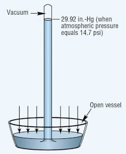
Atmospheric pressure is measured with a barometer. A barometer consists of an evacuated vertical tube with its top end closed and its bottom end resting in a container of mercury that is open to the atmosphere, Figure 1. The pressure exerted by the atmosphere acts on the exposed surface of the liquid to force mercury up into the tube.
Sea level atmospheric pressure will support a mercury column generally not more than 29.92-in. high. Thus, the standard for atmospheric pressure at sea level is 29.92 in.-Hg, which translates to an absolute pressure of 14.69 psia.
The two basic reference points in all these measurements are standard atmospheric pressure and a perfect vacuum. At atmospheric pressure, the value 0 in.-Hg is equivalent to 14.7 psia. At the opposite reference point, 0 psia, — a perfect vacuum (if it could be attained) — would have a value equal to the other extreme of its range, 29.92 in.-Hg.
However, calculating work forces or changes in volume in vacuum systems requires conversions to negative gauge pressure (psig) or absolute pressure (psia).
Atmospheric pressure is assigned the value of zero on the dials of most pressure gauges. Vacuum measurements must, therefore, be less than zero. Negative gage pressure generally is defined as the difference between a given system vacuum and atmospheric pressure.
Types of Vacuum Measurement Gauges
Several types of gauges measure vacuum level. A Bourdon tube-type gauge is compact and the most widely used device for monitoring vacuum system operation and performance. Measurement is based on the deformation of a curved elastic Bourdon tube when vacuum is applied to the gauge's port. With the proper linkage, compound Bourdon tube gauges indicate both vacuum and positive pressure.
An electronic counterpart to the vacuum gauge is the transducer. Vacuum or pressure deflects an elastic metal diaphragm. This deflection varies electrical characteristics of interconnected circuitry to produce an electronic signal that represents the vacuum level.
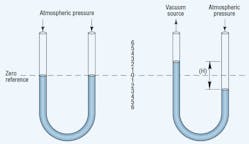
A U-tube manometer, Figure 2, indicates the difference between two pressures. In its simplest form, a manometer is a transparent U-tube half-filled with mercury. With both ends of the tube exposed to atmospheric pressure, the mercury level in each leg is the same. Applying a vacuum to one leg causes the mercury to rise in that leg and to fall in the other. The difference in height between the two levels indicates the vacuum level. Manometers can measure vacuum directly to 29.25 in.-Hg.
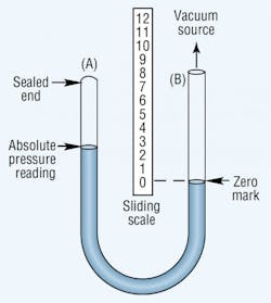
An absolute pressure gauge shows the pressure above a theoretical perfect vacuum. It has the same U-shape as the manometer, but one leg of the absolute pressure gauge is sealed, Figure 3. Mercury fills this sealed leg when the gauge is at rest. Applying vacuum to the unsealed leg lowers the mercury level in the sealed leg. The vacuum level is measured with a sliding scale placed with its zero point at the mercury level in the unsealed leg. Thus, this gauge compensates for changes in atmospheric pressure.
Categories of Industrial Vacuum Systems
Vacuums fall into three ranges:
- rough (or coarse), up to 28 in.-Hg
- middle (or fine), up to one micron,
- high, greater than one micron.
Almost all industrial vacuum systems are rough. In fact, most lifting and workholding applications operate at vacuum levels of only 12 to 18-in.-Hg. This is because it generally is more economical to increase the lifting or holding force by increasing the contact area between the workpiece and vacuum cup than it is to pull a higher vacuum and use the same contact area.
Middle vacuum is used for process applications such as molecular distillation, freeze drying, degassing, and coating operations. High vacuums are used in laboratory instruments, such as electron microscopes, mass spectrometers, and particle accelerators.
A typical vacuum system consists of a vacuum source, delivery lines, fittings, and various control valves, switches, filters, and protective devices. Leakage prevention is especially important with vacuum systems because even very small leaks can greatly diminish performance and efficiency. If plastic tubing is used — as is often the case — be sure it is designed for vacuum service. Otherwise, the walls of the tubing could collapse under a vacuum and block flow. Also, vacuum lines should be as short and narrow as is practical to limit the volume of air that must be evacuated.
An important design consideration for workholding applications is to use the vacuum pump only to achieve the vacuum level required. Once the workpiece is in contact with the vacuum cup and the required vacuum achieved, de-energizing a normally closed valve will hold the vacuum indefinitely - provided no leakage occurs. Holding a vacuum in this manner consumes no energy and avoids having to operate the vacuum pump continuously.
Companies also offer proprietary devices, such as vacuum cups with integral valves and valves that terminate flow from a cup that exhibits excessive leakage. This valve is designed to avoid false-alarm shutoff when holding porous workpieces (such as cardboard), yet prevent a leak at one vacuum cup from reducing vacuum at an adjacent cup.
Proper Vacuum Pump Selection
The first major step in selecting the right vacuum pump is to compare application vacuum requirements with the maximum vacuum ratings of commercial pumps. At low levels, there is a wide choice of pumps. But as vacuum level increases, the choice narrows, sometimes to the point where only one type of pump may be available.
To calculate a system's vacuum needs, consider all work devices to be driven. The working vacuum of the devices can be determined by calculations based on handbook formulas, theoretical data, catalog information, performance curves, or tests made with prototype systems. Once you know the vacuum required, you can begin looking for pumps that can accommodate application requirements.
Temperature considerations are very important when selecting a mechanical vacuum pump because high external or internal heat can greatly affect pump performance and service life. Internal pump temperature is important because as vacuum level increases, less air is present to carry away the heat generated, so the pump must absorb more of the heat.
Heavy-duty pumps with cooling systems are often required for high vacuum applications. But light-duty pumps can operate at maximum vacuum for short periods of time if there is an adequate cool-off period between cycles. The pump experiences a total temperature rise as a result of all the heat sources acting on it - internally generated heat plus heat from internal leakage, compression, friction, and external ambient temperature.
Venturi-Type Vacuum Pumps
Many machines that require vacuum also use compressed air. And if vacuum is required only intermittently, the compressed air that already is available can be used to generate vacuum through a device called a vacuum generator, also known as a vacuum ejector or vacuum pump.
Furthermore, the compressed air also can be used in combination with a vacuum cup by producing a puff of air to hasten release of the workpiece.
Vacuum generators operate based the venturi principle, Figure 4. Filtered, non-lubricated compressed air enters through inlet A. A diffuser orifice (nozzle), B, causes the air stream to increase in velocity, thereby lowering its pressure, which creates a vacuum in channel C. The air stream exhausts to atmosphere through muffler D.
Vacuum generators offer several advantages. They are compact and lightweight, so they often can be mounted at or near the point of use. They are inexpensive, and because they have no moving parts, do not require the maintenance associated with mechanical vacuum pumps. They do not need an electrical power source because they generate vacuum by tapping into an existing compressed air system. However, if retrofitted into a machine, capacity of the existing pneumatic system may have to be increased. Heat generation, which often is the limiting factor with mechanical vacuum pumps, is of little concern with vacuum generators.
Mechanical pumps most often are specified to provide a machine with vacuum on a continuous basis. But many of these machines actually use vacuum only intermittently at many different locations. In cases like this, vacuum generators can provide a practical alternative by supplying vacuum intermittently at each source rather than continuously for the entire machine.
Vacuum generators are controlled simply by initiating or terminating compressed air flow to the nozzle. Vacuum generators have been used for decades, but relatively recent improvements have led to nozzle designs that provide higher operating efficiencies.
Another development using venturis is the multi-stage vacuum generators. In this configuration, two or more vacuum generators are piped in series to produce greater vacuum flow without using more compressed air. Essentially, the exhaust from the first nozzle (which determines the maximum attainable vacuum level) serves as input for a second stage. Exhaust from the second stage then serves as input for a third stage. This means that a multi-stage generator evacuates a given volume faster than a single-stage generator does, but they both will eventually pull the same vacuum level.
Selecting a vacuum generator depends on the lifting force required and the volume of air that must be evacuated. Lifting force depends on the vacuum level the generator can pull — which, in turn, depends on the air pressure supplied — and the effective area of the vacuum cup. In most applications it is important that a generator be able to pull the required vacuum in as short a time as possible to minimize air consumption.
How Long Does it Take to Reach Maximum Vacuum?
When choosing among several vacuum pumps, an important factor may be how long it takes each pump to reach the needed vacuum.
In general, a small capacity pump and a large capacity pump with equal maximum vacuum capabilities will both produce the same vacuum. The smaller pump simply takes longer. How much longer depends on the capacity of the pump and the size of the system. But simply dividing system volume by open pump capacity won't produce the proper answer.
During pump-down, the higher a vacuum becomes, the fewer air molecules remain in the closed volume. Therefore, fewer molecules can be removed by each pump stroke. As a result, there is a logarithmic relationship when approaching a perfect vacuum. The time required to pump a system down to a certain vacuum level can be approximated using this formula:
t = (V×n) ÷ 4q,
where:
t is time, min
V is system volume, ft3
q is flow capacity, cfm, and
n is a constant for the application.
For exact applications, n can be determined by using a natural logarithm. For most purposes, the following will suffice:
n = 1 for vacuum to 15 in.-Hg
n = 2 for vacuum >15 but ≤ 22.5 in.-Hg., and
n = 3 for vacuum ≥ 22.5 and up to 26 in.-Hg.
One additional complication: pump capacity in the equation is not the open capacity (capacity at atmospheric pressure) usually cataloged by manufacturers. Instead, it represents the average capacity of the pump as system pressure drops to the final vacuum level. This value is not readily available but can be approximated from manufacturers' pump performance curves. These curves plot pump capacity at various vacuum levels.
To mesh these curves with the equation, simply substitute values in the equation using pump capacity readings from the curve at various vacuum levels at 5-in.-Hg increments, up to the desired level. Then total these times.
Finally, note that this pump-down time is based on all system components operating at optimum levels. A 25% additional time allowance is recommended to compensate for system inefficiencies and leakage.
How High Altitudes Can Impact Vacuum
Atmospheric pressure determines the maximum vacuum force that can be achieved. And standard atmospheric pressure at sea level is 29.92 in.-Hg. But what happens at locations a mile above sea level?
The maximum vacuum that can be achieved in locations above sea level will be less than 29.92-in.-Hg. The force will be limited by the ambient atmospheric pressure. Vacuum pumps have maximum vacuum ratings based on sea level conditions and must be re-rated for operation at higher elevations.
First, determine the local atmospheric pressure. A rule of thumb is that for every 1000 ft. of altitude above sea level, atmospheric pressure drops by 1 in.-Hg. Using rounded-off figures, for a city at an elevation of 5,000 ft, the atmospheric pressure is about 25 in.-Hg.
To adjust a pump rating, think of that rating as a percentage of atmospheric pressure at sea level. If a pump is rated for 25 in.-Hg, it can achieve 83.4% (25 29.92) of a sea level perfect vacuum. At a 5000-ft elevation, that same pump can achieve 83.4% of 25 in.-Hg - or a vacuum of 20.85 in.-Hg.
