Hiram Moore invented the combine harvester in the U.S. in 1834. The machine combined three separate operations — reaping, threshing, and winnowing — into a single process. But it wasn’t until 1911 that the self-propelled harvester was introduced. Eventually, hydraulics were incorporated to make the machine more versatile and productive. Today’s combines are equipped with removable headers for use with particular crops— wheat, oats, rye, barley, soybeans, etc. Some time before 1973, hydropneumatic accumulators were incorporated into header positioning systems to make combine harvesters even more effective.
A combine’s removable header weighs thousands of pounds and must remain positioned a specific distance above and parallel to the ground during harvesting. Pressurized hydraulic fluid directly from the machine’s hydraulic pump could keep the header suspended, but would consume substantial power from the engine. Instead, accumulators are used in these floating header suspension systems as an energy-efficient alternative. The accumulators also provide damping to smooth out pressure fluctuations that occur when the combine hits a bump, rut, or large rock.
Sizing up the system
The basic header lift hydraulic circuit generally uses two lift cylinders. However, depending on size, some units have one, or up to four. The hydraulic circuits for header lifting have become more complex over the years, including a trend toward using a single circuit for both header lifting and ride control.
Accumulator sizing for these circuits initially used trial-and-error methods. Different sizes and precharges would be tried until one was found that worked best. However, a more systematic approach bases initial sizing calculations on header weight. Once weight is known, pressure to float the header with the lift cylinders can be calculated, which will yield gas precharge pressure in the accumulator. The precharge pressure must be sufficient to balance the weight of the floating header.
Size of the accumulator can then be determined. This calculation must account for allowable travel of the cylinders. Specifically, this relates to a pressure curve to determine how far the cylinder will be allowed to move when a bump or rock in the field is encountered. The amount of cylinder stroke, whether 1, 2, or 3 in., ultimately converts to the size of accumulator needed for that header.
However, what remains is to determine if that accumulator size is best for a given manufacturer’s machine. To do this, extensive field testing with different size accumulators must be conducted to determine the best fit for each header and crop to be harvested. No accumulator sizing formula exists for floating deck applications, so testing is required to make the final determination. But what if a farmer uses different headers for different crops? Another consideration comes into play because a specific accumulator precharge pressure has been determined for use with a specific header. If a farmer installs a different header, match-up problems could occur. A substantially lighter header would make the precharge pressure too high, causing stiff flotation action. Installing a heavier header would cause the flotation action to be over damped.
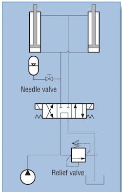
The simplified schematic of an accumulator circuit for a typical floating header is shown above, left. The needle valve is adjusted to change the flow rate between the circuit and accumulator to use headers with different weights.
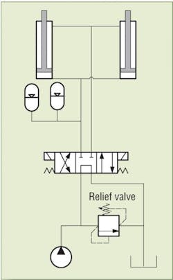
Another solution is to incorporate two piston accumulators with different precharge settings into the circuit. This approach allows the farmer to use both headers for different crops without having to make accumulator adjustments. One accumulator will float the weight of the one header. For example, when that header is removed and replaced with a heavier one, the second accumulator becomes active in the circuit. The piston accumulator with the lighter precharge will collapse quite a bit to allow the second accumulator to take over. Bladder accumulators should not be used in dual applications because the bladder could potentially be damaged with an immediate and sudden failure.
A new approach
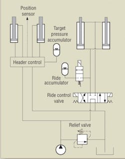
Today’s new approach to combine header flotation uses separate accumulators used for float and lift cylinders. For flotation, a ground clearance distance sensor is used with a sophisticated electronic control to automatically adjust header height during harvesting. The circuit includes a target pressure accumulator. As the header is lowered to the ground and the system is set to maintain a specific float distance, the accumulator serves as a memory device to automatically make needed adjustments if the target pressure changes.
New header designs also feature a separate set of lift cylinders with a ride control accumulator that can be activated when the combine header is lifted to permit driving to the next work area. Incorporating the accumulator completely eliminates the problem of machine bouncing as it is driven down a road.
What size and type?
Both bladder and piston accumulators work well in flotation applications. Neither type has an advantage, except in the previous example when two accumulators are used in the circuit.
Early hydraulic flotation systems were designed for high flow at low pressure, which required large cylinders with large volumetric displacement. Accumulators for these systems were typically 170 in.3 to 1 gal in size. In today’s flotation applications, accumulators are only about 1⁄4 gal in size because the hydraulic systems are designed for lower flow at higher pressures. This, in turn, reduces the size and volumetric displacement of the cylinders. It is a closed circuit on the cylinder side where the accumulator is located.
Edward Godin is Technical Services Manager at Parker Hannifin Corp., Global Accumulator Div. For more information, visit www.parker.com/accumulator or call (815) 636-4100.

