One of our readers recently wrote me regarding the following problem:
"I tried one afternoon and evening to determine what was wrong with a hydrostatic transmission by monitoring case drain flow and was confused by the readings I was seeing. There was a flow meter in the transmission pump outlet and another in its case drain that always showed charge pump flow, even though the motor was bypassing profusely. The motor case drain went through the transmission pump case to tank."
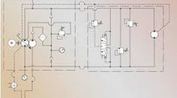
Recall that a hydrostatic transmission consists of a variable-displacement pump and a fixed or variable displacement motor, operating together in a closed circuit. In a closed circuit, fluid from the motor outlet flows directly to the pump inlet, without returning to the tank.
As well as being variable, the output of the transmission pump can be reversed, so that both the direction and speed of motor rotation are controlled from within the pump. This eliminates the need for directional and flow (speed) control valves in the circuit.
Because the pump and motor leak internally, which allows fluid to escape from the transmission loop and drain back to tank, a fixed-displacement pump called a charge pump is used to ensure that the loop remains full of fluid during normal operation. The charge pump is normally installed on the back of the transmission pump and has an output of at least 20% of the transmission pump's output.
In practice, the charge pump not only keeps the transmission loop full of fluid, it pressurizes it to between 110 and 360 PSI, depending on the transmission manufacturer. A simple charge pressure circuit comprises the charge pump, a relief valve and two check valves, through which the charge pump can replenish the transmission loop. Once the loop is charged to the pressure setting of the relief valve, the flow from the charge pump passes over the relief valve, through the case of the pump or motor or both, and back to tank.
What is the significance of case drain flow?
When a pump or motor is worn or damaged, internal leakage increases and therefore the flow available to do useful work decreases. This means that the condition of a pump or motor can be determined by measuring the flow from its case drain line (internal leakage) and expressing it as a percentage of its theoretical or design flow.
When applying this technique to a hydrostatic transmission, charge pump flow must be considered. In most transmissions, the charge pump relief valve vents into the case of either the pump or the motor. This means that in the circuit described by our reader, where the motor case drain flushed through the transmission pump case to tank, you would expect to see the flow meter in the transmission pump case drain line reading design charge pump flow. Here's why:
Say charge pump flow was 10 GPM, of which 4 GPM was leaking out of the loop through the motor's internals (case drain) and 2 GPM was leaking out of the loop through the pump's internals. The balance of 4 GPM must therefore be going over the charge relief - but still ends up in either the pump or motor case, depending on the location of the relief valve. In this particular circuit, because the motor case drain flushed through the transmission pump case to tank, you would expect to see the flow meter in the transmission pump case drain line reading the sum of these three flows (10 GPM).
Before any meaningful conclusions can be drawn, the case in which the charge pump relief is venting (motor or pump) must be determined and the two case drain lines (motor and pump) must be isolated from each other. If the charge relief vents into the case of the pump, then it is possible to determine the condition of the motor by measuring its case drain flow, but not the pump. If the charge relief vents into the case of the motor, then it is possible to determine the condition of the pump by measuring its case drain flow, but not the motor.
It is not possible to determine the condition of the component that has the charge relief valve venting into it because there is no way of telling what proportion of the total case drain flow is due to internal leakage - unless of course the charge relief can be vented externally while the test is conducted. While it is possible to do this on some transmissions, it's not an easy or simple exercise.
Bottom line: using case drain flows to determine the condition of the components of a hydrostatic transmission, without thoroughly understanding the configuration of closed circuits, can result in incorrect conclusions and the costly change-out of serviceable components. And to discover six other costly mistakes you want to be sure to avoid with your hydraulic equipment, get "Six Costly Mistakes Most Hydraulics Users Make... And How You Can Avoid Them!" available for FREE download here.

Continue Reading
Continue Reading
Case Drain Issues with Pumps and Motors
Oct. 28, 2021
Sponsored Recommendations
Sponsored Recommendations
All-In-One DC-UPS Power Solutions
March 13, 2024
Motor Disconnect Switches
March 13, 2024
Industrial Straight-Through Cable Gland
March 13, 2024
