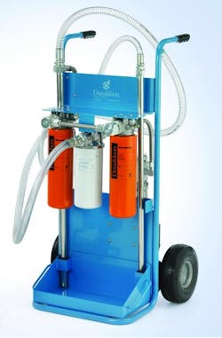
Maintaining clean fluid in any hydraulic system requires capturing and removing contaminants, this is typically done by filtering the fluid. But to be done successfully, filtration must not disrupt fluid flow or substantially increase the pressure drop within the system. It’s a delicate balance between system design and efficiency.
Research and development efforts for hydraulic filtration of the future focuses on three major areas:
- developing the technology to produce finer fibers in filter media,
- engineering the geometries of filter media for maximum effect, and
- improving the overall construction and design of the filter to maximize the useful filtration area for optimal performance.
The simplest form of filter is a sieve, sometimes called a screen or strainer. The sieve works by allowing fluid and small particles to pass through, but trapping particles larger than the holes in the screen. Depth media, the popular choice for hydraulic filters, consist of multiple strands of fibers laid down randomly. The layers effectively reduce the size of passages through which fluid flows, thereby trapping particles smaller than a single layer of screen. Depth filters then have the potential for higher efficiency and to hold more dirt than simple strainers.
Two basic principles are commonly applied to improve efficiency of depth filters. One can either add more layers to the filter in an attempt to catch any particles that make their way through the surface layers, or make the pore spaces finer by compacting the media during the manufacturing process. Modern filter media design often combines layered combinations of coarse media with finer grades. The intent is to capture the larger dirt particles on the courser surface layer, and trap the finer particles within the finer media.
Improving efficiency by increasing the number of layers or making pores finer, however, can have some undesirable consequences. Both methods can lead to an increased differential pressure across the filter as it fills up with dirt. When this occurs, hydraulic filters generally have a bypass circuit. This causes oil to be routed around the filter, rather than through it, once the pressure across the filter builds to a predetermined level. As pressure builds across the filter over time, caused by contamination, the filter element must be periodically changed to prevent dirty oil from bypassing the filter.
Finer fibers hold more dirt
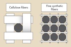
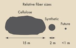
To improve element life and reduce pressure drop across the filter element, filter manufacturers are continually looking for materials that have finer fibers. The goal is to provide more pore spaces to capture the dirt without decreasing the fluid flow area, Figure 1. Traditionally, most depth filtration media were made using cellulose (paper) fibers. Today, many hydraulic filters are made with man-made fibers of smaller diameter, Figure 2.
Future technology will most likely continue to produce even finer fibers. For example, cellulose fibers typically range in diameter as small as 15 μm. Synthetic fibers, however, routinely are manufactured with diameters below 1μm.
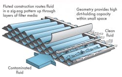
But research and development efforts for hydraulic filters are not limited to new media materials. Manufacturers also are experimenting with new geometries and orientations of media to increase filter capacity and rigidity of construction. For example, Donaldson Co. is developing fluted construction, Figure 3,which provides alternating flow paths and allows more filter media per unit volume. In the future, this type of construction could replace the pleated designs that are used so extensively in hydraulic filters.
Filter efficiency
Filtration efficiency is normally expressed as the ratio of dirt entering a filter compared to the dirt exiting the filter of a specified size. The testing of filters is done under precisely controlled laboratory conditions so the results can be compared and statistically verified. Filtration tests attempt to accurately control the quality of the test dust, the flow rates, temperatures, measuring equipment and many other variables in order to ensure the repeatability of the test.
It is understandable that filters do not always perform in the field just as laboratory tests would suggest. Issues contributing to poor filter performance can include pulsating or surging flows, start-up contamination, and overall design flaws within the hydraulic system.
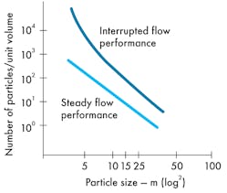
Pulsating flow — In the laboratory, filters are tested under steady state flow conditions. With the pulsating flow of real-world applications, significant reductions in performance can be experienced, Figure 4. Furthermore, if the magnitude and frequency of pulsations are great enough, they can actually cause premature failure of the filter. Therefore, precautions should be made to install filters to avoid subjecting them to pulsating flow.
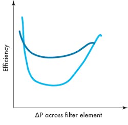
Not only can efficiency vary with pulsating flow, but also different configurations of media can cause different efficiencies at increasing differential pressures. For example, Figure 5 depicts two elements that have the same micron rating (average efficiency) but differing maximum and minimum efficiencies and, consequently, varying dirt-holding capacity. The final point on the graph depicts element collapse.
Reaching a conclusion
As explained here, several factors, other factors can influence a system’s integrity-proper handling and a solid system design go a long way toward solving dirty oil problems. Each situation is different — with varying climates, environments and cleanliness requirements to take into consideration.
However, a knowledgeable distributor or consultant will be able to accurately diagnose systems and recommend which media choices, filter types, and filter positioning are right for every application.
Without question, the single biggest improvements to hydraulic filtration have come from firstly installing clean fluids, secondly preventing further ingress of contaminants through breathers and seals and thirdly installing filters on equipment in positions where the flow remains as constant as possible during operation of the equipment. Avoiding “stop start” typical return flow conditions can significantly improve system cleanliness levels. If flow is continually starting and stopping through a depth type filter media it will render the filter virtually useless in capturing particulate below ten microns.
Stopping contamination at its entry point — the reservoir
The amount of generated contamination in a hydraulic system is usually fractional compared to contamination ingression. Much of this ingression occurs at the reservoir, so good reservoir design targets the dirt at the source of handling errors.
The modern trend in reservoir design is to keep the reservoir as small as practicable. This reduces the cost of construction and amount of fluid needed, and enables the oil to be more regularly recycled through the hydraulic system’s filters. The more frequently oil is cycled through a filter, the cleaner it becomes. Therefore, with a smaller reservoir, the oil tends to complete the filter cycle more often. One disadvantage to a small reservoir is that the oil can become too hot unless auxiliary cooling is provided. As the reservoir becomes too hot, oil oxidizes, which can shorten the life of the oil.
One reason for a large reservoir may be to ensure there is sufficient oil to shut down an operation in case of an emergency. This is more typical on heavy rotating machinery where it can take several minutes to stop. Not having enough fluid reserve could cause catastrophic failure. Large reservoirs generally require larger filters and regular recirculation to effectively control contamination.
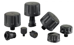
Breathers — Tank breathers are a critical component for good filtration on most hydraulic systems. At inlet sites, where the system is open to the atmosphere, there is significant potential for contamination. Sometimes, sealed and pressurized reservoirs can negate the need for breathers altogether by preventing dirt from entering the system. However, pressurized tanks are more suitable for smaller reservoirs with stable flow and level conditions. In most cases, breathers will be necessary to maintain the cleanliness of a hydraulic circuit to prevent ambient dirt from entering the system.
Although most systems are designed with the breather inlets on the top of the reservoir cover, it is often more effective to design the tank with inlets on the side (above oil level). With gravity, it is easier for dust, water and other contaminants to fall into top openings — especially during cleaning, filling, etc. This tendency is naturally reduced when the inlet is on the side of the tank. Although side inlets require the additional expense of a filling device, this can be a small investment compared to the added benefits of reducing the contamination.
Ideally, a breather should prevent atmospheric particles larger than 5 μm from entering the system. Typically a good quality liquid filter with a 10 μm absolute rating will perform well at removing 5 μm and smaller dust particles from air.
A properly sized breather should also allow sufficient air movement. An undersized reservoir breather, especially on large tanks, can easily cause a tank to split or collapse by restricting air flow.
In applications where condensation is common — paper mills, bulk storage tanks, food processing plants, and a variety of other environments — many engineers rely on breathers containing a desiccant that absorbs moisture before it can enter the reservoir. However, if the breather’s filter element and desiccant are not kept clean, the desiccant can become the contaminant if the separating filter media is not capable of capturing dirt particles larger than 5 μm.
The next time you conduct a reservoir inspection, see if your breather has a filter inside it. A wire mesh that you can see through is not adequate to control 5 μm dirt particles, Check to see if the seal on the filler cap actually seals air tight, and check to see if there any open pipes, bolt holes, or unsealed covers. Dirty air will take the path of least resistance into the reservoir — eventually causing damage to the hydraulic system.
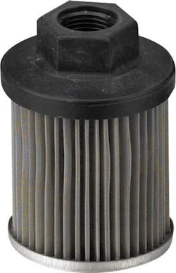
Suction filters — In the hydraulic circuit, suction filters are normally placed between the reservoir and the pump. Typically, they are designed to remove dirt particles ranging in size from 5 to 10 μm. Suction filters should not be confused with suction strainers, which serve little purpose other than to keep nuts, bolts, weld spatter, cigarette butts, and other large objects out of the pump.
It’s critical to size and maintain suction filters well. If the filter lets contaminants pass through into the pump, the pump will fail. If the filter becomes blocked, it can cause the pump to cavitate. The result will be the same — pump failure and further damage downstream of the pump.
The most popular application for suction filters is with variable-speed hydrostatic pumps, often found in mobile equipment and industrial variable-speed hydraulic drives. Suction filters used in conjunction with this type of pump will normally cause the pump to stall when blocked — before any damage
is caused by the inlet flow restriction.
Each pump manufacturer has strict criteria regarding inlet flow restrictions. These should be followed carefully when applying suction filtration. Generally, try to avoid suction filters with high flow rate pumps, particularly gear and vane pumps. Instead, clean the oil before it gets to the pump.
Offline (kidney loop) filters— Kidney loop filtration can be one of the most effective ways of cleaning a hydraulic system and keeping it clean. One advantage to this type of filtration is that the oil flow is nearly constant, which promotes the most efficient and reliable filter performance. Another is that the filter circuit can be serviced without having to shut down the entire system.
When using a kidney-loop filter, an additional pump is usually required at the inlet site. Considering this additional cost, built-in kidney loop filters are perhaps better suited for applications with large reservoirs of oil, or in hydraulic systems with particularly expensive components, such as servovalves. For small-tank applications, it probably makes more sense to use a mobile filter cart, which can move from one system to the next.
Careful positioning and connection of the kidney loop filter is very important to avoid stirring up dirt that may already be in the system. Ensure that the tank has proper inlet and outlet fittings that connect to the filling hoses.
With careful design, a kidney filtration unit can also be used to filter oil during the filling of the reservoir. Because a kidney filtration system does not take the full flow of the hydraulic system, and simply dilutes the dirt in the oil reservoir, aim to use the finest filtration practicable. Generally, 5 μm absolute filtration is optimal, depending on the application and the oil viscosity.
Philip Johnson is Industrial Hydraulics Director, Donaldson Co. Inc., Minneapolis. For more information, visit www.donaldson.com.
