Hydraulicspneumatics 1562 Troubleshooting1

Troubleshooting Challenge: Unexpected Pressure Loss while Testing A New Hydraulic Power Unit

Nov. 13, 2014
In preparing for a retest of a hydraulic power unit experiencing quick pressure drops/rises, the oil was drained from the reservoir and panels removed, only to discover construction debris and beads of excess pipe dope at the bottom of the reservoir.
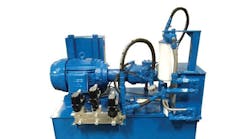
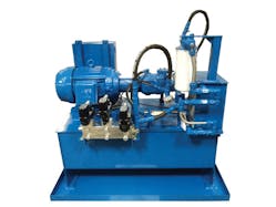
When I was manager of a large hydraulic power unit (HPU) fabrication shop, we had a strange problem while testing a large HPU. It consisted of a large vane pump, a pilot-operated relief, and a 5-bank D08 manifold with 3-position blocked center directional valves with pressure reducing modules. All the A and B ports contained pressure gauges. The HPU had a separate off-line filtration and cooling circuit, which we commonly refer to as a kidney loop. The pump was driven by a 100-hp, 1800-rpm electric motor — a large HPU, but a fairly simple system.

The system pressure was set to 2250 psig with an output flow of 75 gpm. The pump would run for 30 to 60 seconds at a time under pressure, but then all pressure would quickly drop to near 0 psig for 2 to 3 seconds. Pressure would then quickly jump back up to 2250 psig. This happened 15 to 20 times before the test mechanic called me for help.

The unit piping had about ½-in. NPT and ½-in. O-ring connections. No Teflon tape was used, just white, paste-type pipe dope for sealing the NPT connections. We felt the only valve that could cause the malfunction was the pilot-operated relief, so we dis-assembled and inspected it. We did this at least four or five times and could not see any contamination or sticking problem.

We were pressed to move onto other units on the test stand, so we drained the oil from the reservoir and removed its access panels, with the eventual plan of retesting it later. However, we noticed that the reservoir bottom was covered with typical construction debris and a rather large amount of small beads of excess pipe dope.

Any idea what was causing the problem?

Download this article in .PDF format
This file type includes high resolution graphics and schematics when applicable.

Solution to last month’s problem: Hydraulic system causes structural failure

Click on image for larger view.

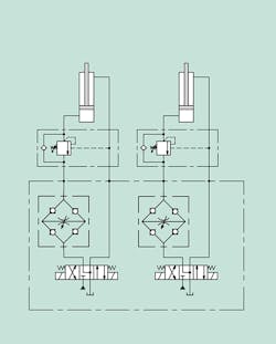
The circuit design was intended to have the same speed lifting and lowering. The designer used a pressure and temperature-compensated flow control with 4-check valves arranged similar to an electrical “Diode bridge.” This always directed the oil flow coming from either direction through the flow control’s entry port. One of the checks failed open due to a contamination problem and allowed the oil to bypass the flow control and consequenty drop 60,000 pounds of steel coil 18” to a sudden stop.
About the Author

Robert Sheaf | President

Robert J. Sheaf Jr., is the founder and president of CFC Insustrial Training, formerly Certified Fluid Consultants, part of CFC-Solar Inc. CFC-Solar provides technical training, consulting, and field services to any industry using fluid power technology. 

Continue Reading

Motor leakage variations

Oct. 18, 2006
affect low-speed performance

The Impacts of Electrification on Fluid Power Systems

May 15, 2023
Electrification presents challenges as well as opportunities to re-evaluate and improve upon the design of hydraulics and pneumatics.

Sponsored Recommendations

7 Key Considerations for Selecting a Medical Pump

Feb. 6, 2024
Newcomers to medical device design may think pressure and flow rate are sufficient parameters whenselecting a pump. While this may be true in some industrial applications, medical...

How Variable Volume Pumps Work

Feb. 6, 2024
Variable volume pumps, also known as precision dispense pumps, are a positive displacement pump that operates by retracting a piston to aspirate a fluid and then extending the...

What is a Check Valve and How Does it Work?

Feb. 6, 2024
Acheck valve, a non-return or one-way valve, is a mechanical device that allows a gas or liquid to flow freely in one direction while preventing reverse flow in the opposite ...

The Difference Between Calibrated Orifices and Holes

Feb. 6, 2024
Engineers tasked with managing fluid flow talk about both holes and calibrated orifices, but they are two distinct entities. A hole can be any opening, but a calibrated orifice...