Aquamarine Power, based in Edinburgh, Scotland, is an alternative energy company with additional operations in Ireland and Northern Ireland. It is currently developing its flagship technology, a hydroelectric wave-energy converter called Oyster. Aquamarine Power’s goal is to develop commercial wave farms around the world to make renewable marine energy commonplace. Intended design life is about 25 years — a key reason designers chose hydraulics to transmit power. Developers don’t expect the systems to be maintenance-free for 25 years, so the design must allow divers to replace major components every 5 years.
Power-plant basics
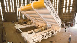
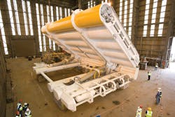
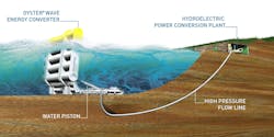
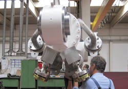
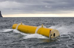
The Oyster power plant sits on the sea floor and features a large (12 × 26 m), bottom-hinged buoyant oscillator. The plant would typically be located in 12- to 20-m of water to interact with surge forces encountered in near-shore areas. The surge forces move the oscillator like an inverted pendulum, which can pivot a full 180°. The oscillator is connected to a pair of hydraulic cylinders that transmit power from the waves as hydraulic power. Each stroke of the cylinders pushes hydraulic fluid (in this case, 95-5 water-glycol) to shore through piping, where the pressurized fluid drives a turbine to generate electrical power.
In 2009, Aquamarine deployed Oyster 1, a 315 kW near-shore wave energy prototype, at the European Marine Energy Centre (EMEC) in Scotland. The prototype became the world’s first grid-connected electrical power generator from a near-shore wave energy device. With a design life of two years, Oyster 1 was decommissioned in 2011.
One of the challenges encountered during the operation of Oyster 1 was reliability of the cylinder seals. Consequently, design efforts for subsequent systems have focused on longevity and ease of maintenance.
The next-generation unit, Oyster 800, represents a step change in design, size, and power output. The oscillator is about 50% wider than Oyster 1 but produces about 250% more energy because of hydrodynamic design optimization. Oyster 800 will form part of an array comprising three wave-energy converters which will be connected to a single onshore hydroelectric plant. The set-up will dramatically improve the plant’s overall economics.
Cylinder design
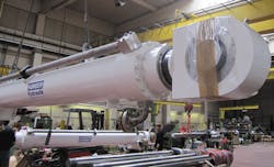
The hydraulic cylinders had to be designed to operate in an underwater environment where servicing or even a simple seal change is difficult. During the specified system lifetime of 25 years the cylinders will experience approximately 120 million cycles. But to keep the system running, a five year service period is planned for the final Oyster system — which corresponds to 24 million cycles. Therefore the typical wear parts of the cylinder have to be designed to last this long. Additionally, the design had to be easy to service and offer the possibility of refurbishing the main components.
System pressure under full load is 120 bar with pressure peaks up to 160 bar. This might not be extreme but considering the numbers of cycles, fatigue calculations led to a comparably strong design.
To protect the marine environment, the hydraulic fluid for the cylinders and onshore Pelton turbine is a 95% water-based hydraulic fluid. In addition, partial contamination of the fluid with seawater has to be tolerated by the entire system. This requires good corrosion protection of all inner cylinder parts. The piston rod is coated with an offshore-approved Ultraplate layer and the cylinder bore surface has a stainless steel liner for long-term corrosion and wear protection. Also the seal and bearing elements are designed to tolerate the limited-lubrication properties of a water based hydraulic fluid.
Piston-rod coating
The Ultraplate piston rod coating, a plasma transferred arc (PTA) welded overlay on the piston rod, provides excellent corrosion and wear properties under offshore conditions. In other words, a powder material is plasma welded to the substrate material. The result is a non-porous layer, highly bonded to the base material and offering excellent seawater resistance and good wear resistance.
Ultraplate provide corrosion protection in hard offshore applications like splash zones and submerged conditions according to EN ISO 12944.2. Its capabilities have been tested and proven by many applications for more than ten years. For example, the performance of Ultraplate coating has been tested and certified by Det Norske Veritas (DNV) with regards to layer composition, hardness and corrosion resistance according to the ASTM G48 pitting corrosion test.
Composite tube
To protect the cylinder bore surface against corrosion, a thin stainless-steel liner is installed in the carbon-steel cylinder barrel. The stainless-steel liner doesn’t provide any stability to the cylinder but offers reliable corrosion protection and good wear resistance. To get a rigid connection between the inner liner and outer barrel, both elements were distorted together on a special tube-drawing machine.
Using a piston-shaped tool, which is drawn through the pre-fitted tubes, both were expanded in a way that after releasing the stress behind the piston, the two tubes clamp together gap-free as a composite tube. After the drawing process, the ends of both pieces are sealed by machining and welding together. After that, the liner bore surface is honed like a standard tube to the specified surface quality. Besides very good corrosion properties, another advantage of such a composite tube is that it can be removed and exchanged with a new one in case of damage in the liner surface. Oyster’s 590-mm bore cylinder barrels were produced this way.
Seal and guiding system
The seal and guiding system of the Oyster cylinders require long life, good service accessibility, and chemical compatibility, and tolerate pollution, the possibility of biological growth on the rod surface, and reduced lubrication properties of the fluid. To achieve this, modified seal and guiding elements from the Hunger DFE program were used.
The first internal element is a wiper, to help prevent fluid penetration into the seal and guiding system. Small bypass drill holes prevent a pressure differential across the wiper element. The piston rod is guided by material-modified FI bearing rings. They have a special step-shaped profile that offers an increased support surface against displacements in the direction of motion, and greater clearance between the piston rod and the cylinder head. Even under high side-load conditions or advanced wear on the guide elements, this ensures sufficient clearance to avoid metal-to-metal contact. The material used in the FI bearing elements also guarantees emergency running properties even without fluid.
The sealing system consists of two Hunger TDI-type seals. The first seal on the pressure side is the main seal, followed by an identical second TDI. Whereas the pressurized main seal will show the expected wear behavior, the secondary seal runs non-pressurized with less wear as long as the main seal is fully functional. If the main seal wears out, the secondary seal will still have remaining wear capacity to seal the cylinder. The intention behind this concept is not to have a 100% sealed system but rather an extended life span.
The two TDI seals are followed by an externally adjustable seal system, termed EVD. This spare seal consists of a seal element which is installed with no pretension to the piston rod and an activation unit. This system offers the opportunity to reseal the cylinder in case of worn out TDI seals. To activate the system, a diver must turn the cap of the injection unit mounted to the cylinder head and pressurize it with a special gel. The seal lip of the EVD seal will press against the piston rod surface and reseal the cylinder.
The next three elements, an outer TDI seal, a wiper, and an outer stainless steel scraper share the tasks to keep out sea water, wipe off smaller contaminants from the rod, and break away hard particles and debris.
Seal test rig
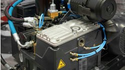
To find the right seal profile and seal material, long-term tests were run. To test the seal elements before installation in the Oyster system, a scaled test rig was designed and built to simulate the main operation and environmental conditions of the seals. The rig consists of a speed-controlled drive unit with a gearbox and lever arm which drives a piston rod. This simulates the oscillating rod movement by the Oyster flap. The test rod is guided and sealed in a cylinder tube which is pressurized with the 95% water fluid by an accumulator. The entire cylinder body is submerged in a water basin for cooling and to simulate the subsea environment. Test pressures are to 70 bar, and with an adjustable cycle frequency from 0.5 to 0.7 Hz.
The test rig has been used on different seal materials and designs, and has run over five-million cycles so far. For example, initial designs failed after only 30,000 cycles due to worn seal bodies, bypass stream damage, and excessive leakage. Other designs quickly failed due to cavitation and blow-by effects. Learning from these failures, the latest design has run several million cycles with acceptable wear. Current durability tests are ongoing and will be compared to real-life results of the Oyster 800 in the sea.
Outlook
Concurrent with testing of the Oyster 800 system, engineering work on the Oyster 801 is pushing forward. This includes a new cylinder design, based on previous versions, but larger scale and with some detail improvements. Also the seal test rig continues running to gain as much possible data and have a lead over the real system. Plans with the Oyster 801 system are to install two units to allow parallel feeding of hydraulic energy into one generator. More-advanced systems with special hydraulic cylinders are planned in the coming years. Future developments will focus on higher reliability, longer service life, larger overall size, and operation with pure water — possibly with seawater in an open circuit.
For more information, contact Ingo Ruehlicke at Hunger Hydraulics GmbH & Co. KG, at [email protected]; and Dipl. Ing. Matthias Haag, Aquamarine Power Ltd., at [email protected].
Read the original paper with more details on the Oyster technology here.
