Proportional pneumatics is a viable technology for closed-loop motion control. But perhaps it has not been used more extensively because myths from antiquated technology have prevailed.
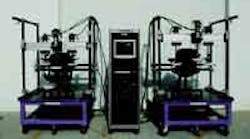
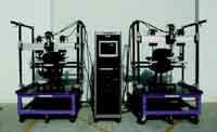
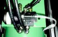
Shown is one of the proportional valves used in Schap's chair testing machine. Seating manufacturers need testing systems capable of replicating varying loads, and pneumatics has the versatility to do this with dynamics that closely match those of human movement. These testing systems must be fast, accurate, long-lasting, and allow for time-compression of the testing process.
Proportional pneumatic motion control systems are used extensively in Europe, but have seen only limited use in North America because of misinformation or incomplete knowledge of their capabilities or how to properly design systems. To give this technology a fair shake, let's explore some of the prevailing the myths of closed-loop proportional pneumatic systems.
MYTH: Pneumatic systems are spongy.
REALITY: Pneumatic systems are perceived to be soft and unable to resist movement when a load changes suddenly. This can be true if the system has not been designed to withstand the forces created by external disturbances. If load changes are expected and the magnitude is known, the cylinder and valve can be sized and selected to provide the necessary restoring force to overcome externally applied forces.
MYTH: Pneumatic systems cannot support heavy loads.
REALITY: Pneumatic systems consisting of a controller, valve, and cylinder must be sized to support and move a load in both vertical and horizontal orientations. After determining the orientation and support structure, the maximum load that can be moved can be determined. From this information, the cylinder bore and stroke can be calculated based on available air pressure and flow. Granted, heavier loads require larger cylinders, higher pressures, or both. Still, a cylinder with an 8 in.-bore has a cap-end piston area of about 50 in.2, so it can produce a theoretical thrust of 11/2 tons from a supply pressure of only 60 psig.
MYTH: Pneumatic systems lack precision.
REALITY: As with any motion control drive technology, proportional pneumatic systems have limitations that are dictated by the response speed of the controlling electronics and physical interfaces — in this case, the valve. If the electronics can detect and resolve the position of the commanded load with a high degree of resolution, and the valve response time is fast enough, the system will come to rest with zero velocity at precisely the commanded position with a measurable error. The error depends on the amount of static friction in the load support system and the acceleration and deceleration speeds versus the dynamic load on the system. These conditions are not unique to pneumatic systems but apply to both electromechanical and hydraulic systems as well.
MYTH: Pneumatic systems are difficult to start and stop at mid-stroke positions.
REALITY: Pneumatic systems can be proportionally controlled to start and stop anywhere between a cylinder's stroke extremes. To achieve this, an intelligent controller and a fast-acting proportional valve are required. The controller must be capable of calculating the precise velocity trajectory profile for the commanded motion and control the valve's output to provide the exact air flow to the cylinder to execute the motion command.
The cylinder must have position or velocity (or both) and pressure sensors installed to monitor motion and load dynamics. This information is processed by the controller and adjustments are made to the valve to either increase or decrease the air flow into or out of the cylinder to force it to remain on the trajectory track. If the trajectory is followed precisely, the motion will follow with the same precision.
MYTH: Pneumatic systems cost more than electric drives.
REALITY: Electric drives range in price from hundreds to several thousands of dollars, depending on the size and sophistication of the motor, controller, and mechanical devices needed to complete the motion control system. Pneumatic systems can be more expensive, but a crossover point exists where a pneumatic system can be less than — and sometimes half the cost of — an electric drive to provide comparable performance.
The crossover point depends on the motion profile and required precision. In general, electric drives are capable of motion control accuracies of ±0.001 in. If the system does not require this closeness of accuracy, then the pneumatic system becomes a more economical choice.
If an electric drive may become cost prohibitive for large horsepower motors, high power controllers, and large mechanical drive systems, then a proportional pneumatic system with multiple actuators may be a more economical choice. To be more specific, pneumatic system accuracies can be as good as ±0.032 in. with a repeatability of ±0.005 in. If this performance is acceptable, then the pneumatic solution may be the most practical choice. Hydraulic drives, on the other hand, can provide more force and power than either electric or pneumatic drives. Generally, though, they cost substantially more and require more maintenance than their pneumatic counterpart.
R. Edwin (Ed) Howe is president, Enfield Technologies LLC, Trumbull, Conn. For more information, e-mail [email protected] or visit www.enfieldtech.com.


