Proportional and servovalves
Infinitely variable directional control valves
The directional control valves discussed so far in this series have all been configured to either pass full flow or completely block flow. The only way to decrease flow through these valves is by adding flow controls or by mechanically limiting movement of an internal part.
The first infinitely variable valve available was the servovalve. Internal flow-modifying parts could be moved to any position at any rate, so output from any port could be varied at will. (Some call these valves infinitely variable 4-way flow controls.) The main problem with servovalves was (and still is) that they require very clean fluid to keep them operating effectively. Fluid from a standard well-maintained hydraulic circuit contains enough contamination to cause most servovalves to fail in a matter of minutes or only last a few hours at best. This meant that the original servovalves were tried and removed from many machines that needed precise control but not at the perceived cost of cleaning up the hydraulic oil.
Why use infinitely variable valves?
Some actuators must move at a precise speed, stop at a close-tolerance position, or produce a very accurate force to perform the work for which they were designed. With the proper input signals and feedback devices, proportional or servovalves can make an actuator perform any or all these functions flawlessly.
Rolling mills turn out sheet consistently to a tolerance of ±0.0005 in. at sheet speeds of 2000 to 5000 feet per minute. Hydraulic cylinders controlled by servovalves maintain the proper force and position the rolls precisely from feedback signals sent by sensors that measure metal thickness, cylinder force, and position. Airline pilots train in simulators moved by hydraulic cylinders so precisely that the pilots get the feel of landing gear raising and locking in position. Even entertainment rides use servovalves to make passengers think they are in 20-ft waves when they are actually in an enclosed articulated room in a shopping mall.
For less precise movement, there are proportional valves that mimic the output of servovalves but respond more slowly. They are less expensive than servovalves and more contamination tolerant, so they have replaced cam valves and other mechanical devices used to get smooth motions.
Hydraulic proportional directional control valves
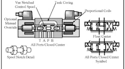
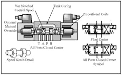
The symbol and cutaway view in Figure 12-1 represent a direct-acting proportional valve that handles flows as high as 10 to 30 gpm in D03- or D05-size valve interfaces. Proportional valves use the same interface standards as NFPA and ISO directional valves so they can be installed in a circuit without having to change the piping.
Physically, proportional valves appear the same as their on/off solenoid counterparts. The big difference is in the way their solenoid coils perform. Proportional coils operate on DC current and produce varying force with varying voltage. The symbol shows the solenoid slash in the operator box with a sloping arrow through the slash. This indicates the solenoid has variable force that moves the spool more or less as voltage increases and falls. The other indication on the symbol that shows the spool is infinitely variable is the parallel lines down both sides of the boxes. Proportional valves operate similarly to manual valves, but they use electronics instead of hand power.
To eliminate flow lag from spool overlap, most manufacturers cut vee notches or use some similar method that allows some flow to pass as soon as the spool moves. Vee notches also give smooth flow buildup until the spool moves through the land overlap.
Proportional valves only have two center configurations (as shown by the symbols in Figure 12-1). This means that pressure-compensated pumps with accumulators normally power circuits with proportional valves. The circuits are pressurized at all times to produce fast response from an actuator when motion is called for. (A pressure-compensated circuit also wastes the least amount of energy when throttling flow.)
The valve in Figure 12-1 depends on a certain voltage to move the spool a certain distance to pass a certain flow. This works reasonably well, but is not accurate over a broad range of pressures, flows, and temperatures. Most valves of this design are used to smoothly accelerate and/or decelerate an actuator. The spool is electronically controlled to shift over a period of time to increase flow at a controlled rate. Spool-shift speed can be controlled electronically as it opens and closes to give smooth acceleration and deceleration. Spool-shift distance can also be limited electronically to set a maximum speed when required.
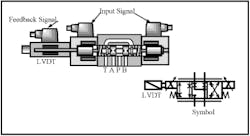
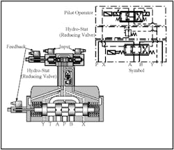
To give better spool control, a linear variable-displacement transducer (LVDT) is added to the basic valve. The cutaway view and symbol in Figure 12-2 represent a direct-acting valve with an LVDT. Feedback from the LVDT tells the electronic controller the spool’s position and makes sure it goes to the same place when it receives the same signal. With this arrangement, the spool always shifts to an exact location and opens the same size orifice so it can pass the same flow when pressure drop and viscosity stay the same. Control of flow is more accurate with an LVDT but pressure drop does not stay constant and viscosity often changes throughout the day so speed variations are still apparent. Such flow variations caused by system pressure fluctuation can almost be eliminated by the addition of a hydrostat module in port P as shown in Figure 12-3.
A hydrostat is simply a pressure-reducing valve set to hold downstream pressure in a 100- to 150-psi range. However, a hydrostat has a pilot line from a shuttle valve that reads downstream pressure at ports A and B, then feeds it back to the bias-spring end of the spool that controls the 100 to 150 psi. The function of a hydrostat is to maintain a constant pressure drop across the spool orifice so flow stays constant regardless of changes in system pressure. (For a thorough understanding of how pressure compensation works, see the pressure-compensated flow control valve section in Chapter 13.)
With the addition of a hydrostat, actuator speed is controlled as accurately as possible without a closed-loop electronic circuit that reads speed and modifies spool position. Closed-loop electronic circuits are used with proportional valve systems, but they only give nominal control. When accurate control is required, use servovalves with closed-loop electronics.
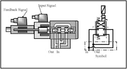
The symbol and cutaway view in Figure 12-4 is for a proportional valve that only controls flow. Such valves are commonly called throttle valves because they are not pressure compensated unless a hydrostat module is added.
Basic operation is identical to the proportional control valves just discussed. The only difference is they have a single solenoid and may be piped with dual flow (as shown). Dual-flow piping allows a given size valve to pass twice the volume at the same pressure drop. It can be used with any 4-way directional control valve with one precaution: the valve must be capable of handling maximum system pressure in its tank port. Many wet-armature valves will not operate at full rated pressure at their tank port. Check the supplier’s catalog to see what maximum tank line pressure is allowed. Air-gap solenoid valves and solenoid pilot-operated valves with external drains normally allow full rated pressure in the tank port.
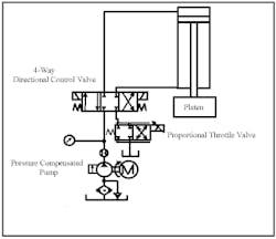
The circuit in Figure 12-5 shows a possible use for a proportional throttle valve. The vertical-down acting cylinder with a platen needs speed, acceleration, and deceleration control. This could be done with a 4-way proportional valve, but the circuit uses an inline or screw-in cartridge valve that is not directly replaceable. Adding a proportional throttle valve to the tank line of the present 4-way circuit can give the required control without extensive piping changes. The circuit is shown using a single flow path for low volume. A dual flow path setup (like the one in Figure 12-4) would allow as much as twice the flow. As stated earlier, make sure the 4-way directional control valve can accept tank-line backpressure without damaging it or causing a malfunction.
If the cylinder had a resistive load, the proportional throttle valve could be placed in the pump line of the 4-way as a meter-in flow-control circuit. A meter-in circuit would not damage the directional control valve or cause it to malfunction. The circuit in Figure 12-5 could have a counterbalance valve in the rod-end line to make it resistive. (See Chapter 14 for counterbalance valve operation and applications.)
The platen would start to move at a controlled rate when the 4-way valve shifts and the proportional throttle valve is signaled to open slowly. The shift time for the throttle valve determines the acceleration time, while shift travel distance determines maximum cylinder speed. Cylinder speed would be infinitely variable to match any production need.
Near the end of the stroke, a slowdown limit switch would signal the proportional throttle valve to start shifting back to its closed position. The proportional throttle valve would close at a controlled rate and flow from the cylinder would be retarded smoothly. When the cylinder slows sufficiently, it contacts the end-of-stroke limit switch and the 4-way directional control valve shifts to center to stop it.
The circuit in Figure 12-5 would only hold position if some retract signal was applied when stopped. This is due to internal leakage by the spool of the 4-way directional control valve and the proportional throttle valve. Another option would be to use a float-center directional control valve and a counterbalance valve.
Proportional valves for flows higher than 25-to-30 gpm use solenoid pilot-operation similar to conventional directional control valves. A small pilot-operated valve receives a signal and then sends hydraulic oil to proportionally move a larger control spool that controls actuator movement.
The cutaway view and symbol in Figure 12-6 depict a typical solenoid-pilot valve arrangement. A reducing valve module, between the pilot operator and the pilot-operated valve, keeps maximum pilot pressure below 200 psi. A proportional Input to one of the coils on the pilot operator directs flow to the spool of the pilot-operated valve and shifts it against a spring. As pressure against the spool increases, it shifts farther and sends more flow to the actuator. Feedback signals from both spools tell the electronic controls that the command has been carried out. A vee-notched spool allows flow to increase at a smooth rate so actuator speed is consistent throughout the speed range.
Ports for internal or external pilot X or drain Y provide options for these control lines to meet a particular requirement.
The complete symbol is shown in Figure 12-6. (For the simplified symbol, see Chapter 4.)
Flows up to 200 gpm are common for a D10-size proportional valve. For higher flows, use slip-in cartridge valves (discussed in Chapter 11) with proportional operators.
Hydraulic servo directional control valves
Proportional control valves are infinitely variable but they are neither highly responsive nor capable of handling minute flow changes rapidly and accurately. On the other hand, servovalves easily meet both of these requirements . . . but at a cost. They are more expensive than proportional valves, they require super-clean fluid, and they need extra electronics to exploit their full capabilities.
The three common servovalve types are flapper, jet pipe, and mechanical. Each design has advantages as far as operation accuracy, leakage, contamination tolerance, and price. They range in flow capacity from less than 1 gpm to more than 1000 gpm. Most manufacturers make valves that operate at 3000 psi, but some offer valves at 5000 psi.
The main difference between proportional and servovalve circuit design is that servo systems have a method of feedback that assures that the actuator is doing what the controller tells it to do. A super-simple form of servo control would be a backhoe operator moving manual valves to cause a bucket to move toward him at a given rate. Feedback from the operator’s eyes would tell his hands when and how far to move the levers to give more or less flow to maintain the action he wants. Other familiar mechanical feedback examples are hydraulic driven power steering and hydraulic power brakes on a vehicle.
The circuit in Figure 12-7 is an example of a working circuit with mechanical feedback that controls a hydraulic press. The operator needs to have a feel for the motion of a platen as it cuts through some tubing. Originally this was done with an arbor press, but it was hard for the operator to keep up with production due to the physical exertion. Now all the operator has to do physically is overcome the spring force of the manually controlled mobile directional valve to make the platen move. As the platen moves, the directional valve body also moves, so the operator has to keep moving the lever to advance or retract the platen. Notice the mechanical link between the valve body and the cylinder rod that moves the valve body at the same rate the cylinder rod moves. The operator now has a hydraulic force multiplier that gives some feel to what he is doing.
The reason for using a mobile-type valve is because those valves have less spool overlap and the spool has notches cut in it. The notches pass a small flow almost immediately when the spool moves. That flow increases in proportion to spool movement.
Most industrial applications use feedback from electronic linear, rotary, or force transducers. A transducer is a device that produces an electrical signal in direct relation to a position, force, or speed.
Linear potentiometers work for short strokes (12 in. or less). Longer strokes require a device such as a Temposonics transducer. In either case, these devices feed a precise position or speed indication back to an electronic controller.
For rotary motion, an encoder or similar device that produces multiple pulses per revolution sends a signal about rpm or angle of rotation to the controller.
When information about force is required, a load cell sends the data to the controller.
With these very accurate feedback devices and a fast-response servovalve, an actuator’s position, speed, and/or force can be repeatedly established within an extremely close range. Electronics provides the accuracy while hydraulics provides the force via a super-responsive servovalve.
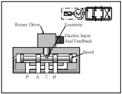
The cutaway view and symbol in Figure 12-8 show a less-responsive but more contamination-tolerant servovalve. There are other mechanical ways of driving the spool. The valve in Figure 12-9 uses a rotary drive and an eccentric to move the spool left or right to an infinite number of positions. Because the drive is quite strong and there are no orifices to clog, this valve can operate with fluid that meets ISO Code 4406 20/16/13.
Notice the difference in design between spools in proportional valves and servovalves. Most proportional valves use spools with overlap and some sort of notches that pass flow while moving out of overlap. A servovalve has no overlap or underlap of the spool lands to the body lands. (One manufacturer calls it “Critical lap” because all points blocking fluid cannot move without passing flow.) This spool design makes the valve very responsive (as well as very expensive and prone to above average bypass). Servovalve spools and bodies always come in matched sets because of their close fit and four points of land-to-land match.
The rotary-drive eccentric valve pictured in Figure 12-8 has fast, controllable spool movement from a rotary drive that incorporates a feedback loop. When the drive receives a signal to move the spool to pass a certain flow, a position feedback output sends a signal back to the controller when the motion is complete. There is still feedback from the actuator that what was commanded is happening, so spool position can be changed via the electronic feedback and controller as necessary.
Several factors determine when a given input will not produce the desired actuator output. The main factor is actuator load. As load changes, input force must change -- by allowing more or less fluid into the circuit. Fluid viscosity also has an effect, so the flow path must be reduced as viscosity lowers and enlarged as viscosity rises. Then there is system pressure. As pressure fluctuates, flow across the spool orifice changes. The higher the pressure drop, the greater the flow. Because a servovalve circuit has feedback from the actuator, it can adjust flow or pressure to match system changes continuously.
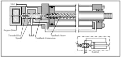
Figure 12-9 shows another mechanically driven servovalve. This setup works for cylinders and hydraulic motors, but must be directly attached to the actuator (as shown) or driven by it with a toothed belt and pulleys. This is a very contamination-tolerant valve arrangement because the stepper motor is quite strong and there are no small orifices to clog. The spool has no overlap or underlap so any movement immediately initiates fluid flow to and from the cylinder. The piston and rod cannot rotate so the feedback screw turns as the piston extends or retracts.
As the stepper motor turns, a threaded rod inside the threaded spool moves the spool to direct fluid to extend or retract the piston. When the cylinder piston moves, the feedback screw turns the spool back on the threaded rod to counteract the stepper motor shift. When the stepper motor turns, the piston moves at a speed proportional to the stepper motor’s rpm. When the stepper motor stops, the piston catches up and stops also. Manufacturers claim a tolerance of ±0.001 in. repeatability. If an external force tries to push or pull the piston out of place, the feedback screw shifts the spool and fluid starts resisting movement.
From the foregoing explanation, it is easy to see how this valve – when attached to a hydraulic motor -- would give an exact number of turns and repeatedly cause the motor to stop at exactly the same place. This will happens even if the hydraulic motor has internal leakage. The only time the actuator gets out of place is when it cannot overcome the load and stalls. The stepper motor continues to receive pulses, but it also stalls when the spool shifts all the way. The stepper motor received a signal that should have placed the actuator at a certain distance but the actuator did not get there because of insufficient force. When the valve reverses, it starts its motion from the wrong point and will overshoot home position as it returns. A limit switch at the home position can alert the controller that there is a problem when the actuator overshoots -- and prevent the machine from producing scrap.
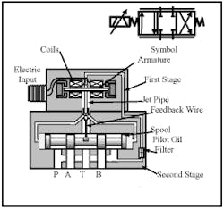
The jet-pipe servovalve pictured in Figure 12-10 also tolerates contamination due to a control orifice that is large enough to pass large particles. Pilot oil is tapped off the system fluid inlet, sent through a coarse filter, and on to the jet pipe that terminates in an orifice. The orifice outlet is centered over the inlet of two passages that terminate at each end of a critical-lap spool. Flow into these passages puts equal pressure on both ends of the spool as the feedback wire holds it centered. Current signals to the coils cause the armature to rotate and shift more of the output of the jet pipe to one passageway than the other. Pressure increases on one end of the spool and decreases on the other end. As the spool shifts, it starts to pass flow to the actuator at a rate set by the input electrical signal.
When the jet pipe shifts to the left, the spool moves to the right. At the same time, the feedback wire also moves to the right, pulling the jet pipe nozzle back to center and stopping spool movement. A given input to the coils electromechanically shifts the armature that moves the jet pipe. This moves the spool hydraulically and forces the jet pipe back to center mechanically through the feedback wire.
A measured electrical input to a servovalve produces a fixed flow output, similar to a proportional valve. This control alone does not give much better control than a proportional circuit even though the valve is more responsive. There is still no compensation for viscosity or pressure changes that can cause the actuator’s speed to fluctuate. To overcome this problem, some sort of electronic feedback from the actuator is necessary. The feedback signal through an electronic circuit board modifies the signal to the servovalve to make the actuator perform as planned. Actually, the electronics do the work as long as the valve can respond quickly enough to keep everything working at the correct rate. This means the spool must be free enough to move easily without excessive bypass. Anytime the spool moves, it should pass flow to and from the actuator.
The valve in Figure 12-10 is considered a 2-stage valve. The first stage is electronic and receives an electronic input signal, while the second stage is fluid powered by a hydraulic signal.
The jet-pipe servovalve depends on clean oil for long trouble-free operation -- not as clean as the requirement for the flapper-valve design discussed next, but clean enough to prevent the jet-pipe nozzle from clogging. It is obvious that once nozzle flow is retarded enough or stops, the valve loses all ability to control flow to the actuator.
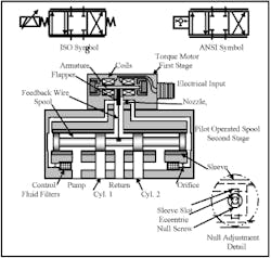
The most responsive and accurate servovalve design is the flapper valve, shown in Figure 12-11. This design is the least tolerant of contamination because it depends on very small orifices for fast response with minimal wasted energy. It is called a flapper valve because the element that holds equal pressure on both ends of the spool at rest reminds one of a flapping device. It is a 2-stage valve with an electronically controlled torque motor as the first stage and a pilot-operated spool as the second stage. As in all servovalves, the spool has no overlap or underlap that would make it sluggish or bypass a lot of fluid unnecessarily.
Fluid from the pump inlet is tapped off through rather-coarse filter elements, passes through orifices past both ends of the spool, goes on to nozzles, and out to the return line. The orifice diameters are slightly larger than the nozzle diameters, so there is a pressure buildup at both ends of the spool. A feedback wire attached to the flapper terminates in a ball end that sits in a very close-fit slot in the spool. A sleeve around the spool can be moved left or right by a null adjustment to align the spool and body lands perfectly when the valve is first installed. (Usually null adjustment is only required at startup of the valve.)
The null adjustment usually is a hexagonal wrench fitting attached to an eccentric pin located in the sleeve slot. With the null adjustment centered, turning it one round moves the sleeve from center to full right, back to center to full left, and back to center. If the valve cannot be nulled within one rotation of the null adjustment, replace it and send it in for repair. This usually indicates a clogged orifice or nozzle controlling one end of the spool.
Unplug the electrical supply to the valve before setting null. Start the pump and watch for actuator movement. If the actuator moves, loosen the null lock screw and carefully turn it. Observe whether the actuator slows or picks up speed. A nulled valve stops actuator movement because the forces on both sides are equal. High-flow 3-stage valves cannot be nulled to the point of stopping an actuator due to the piloted spool slipping by the stop-flow position as the pilot operator is adjusted. When null is set, lock the null screw and reattach the electrical plug.
Turning the null screw with the electric plug detached is one way of moving an actuator manually. This might be done to prove the valve is working properly and the problem is electrical.
When the torque-motor coils receive a current signal, the armature rotates clockwise or counter-clockwise and pushes the flapper closer to one nozzle and farther away from the opposite one. This allows pressure to increase at one end of the spool and decrease at the other. The spool then starts to move away from the higher pressure. If the armature turns clockwise, pressure builds on the left end of the spool and it moves to the right, as shown in the left cutaway view of Figure 12-12.
As the spool moves to the right, it also drives the feedback wire to the right. The feedback wire is strong enough to overcome armature force and pull the flapper back to center. After the flapper centers, pressure is equal on both ends of the spool and it stops. More current to the coils causes more rotation and additional spool shift until the feedback wire again centers the flapper.
From the foregoing explanation, it is obvious why this valve needs clean oil. If an orifice or nozzle clogs, the spool shifts all the way to one end and the actuator moves until it runs into a resistance it can’t overcome. Also, the spool must start shifting at a very low pressure drop across it to keep response high. Contaminated fluid can cause sticking and require high differential shifting pressure that makes spool movement erratic.
For flows above 60 to 80 gpm, a 3-stage servovalve is required. It consists of a small 2-stage pilot operating a large pilot-operated spool, as depicted in Figure 12-13. The 2-stage valve operates as just explained, but its output goes to move a pilot-operated spool in the third stage to a precise position to control high flow to large actuators.
An LVDT signals the electronic control circuit that the pilot-operated spool is where it was signaled to go. After receiving that position signal, the 2-stage valve shifts to no flow or whatever flow it takes to keep the pilot-operated spool in place.
A 3-stage valve also depends on feedback signals from the actuator to modify the input signal when the action is not in compliance with the command. This makes 3-stage valves very accurate controllers of large cylinders.
Pneumatic proportional and servo directional control valves
Since the late ‘80s, several companies have been controlling air cylinders with open- and closed-loop proportional or servovalve circuits. The difference between the air valves in these circuits is how fast they respond. Most proportional valves have a sealed spool that controls direction and flow so the valves tend to hang up and jump. Pneumatic servovalves often have spools with metal-to-metal fits that float on bypass air.
The valve shown in Figure 12-8 is sold as a proportional or servo directional control valve for hydraulic or air circuits. Controlling the amount of air and which direction it goes is not a problem but the compressibility of air creates some giant hurdles to overcome.
Proportional valves usually control only acceleration, deceleration and/or speed because these circuits do not include feedback transducers. It is very easy to get smooth acceleration and deceleration with high speed in between without other controls or shock absorbers to stop the load mechanically.
Adding feedback transducers to a proportional air circuit can provide servo-like control for light loads -- such as those found in pick-and-place applications. However, a proportional valve is usually not responsive enough for exacting part placement or speed control. For very accurate control, a servovalve with feedback transducers can give close-tolerance positioning (with light loads), repeatable velocity control, and very accurate holding force.
Pneumatic proportional and servovalves are not a replacement for electromechanical or servo hydraulics, but they have price advantages over both systems. When the loads are light and cost is a factor, they are worth a look.
General information for hydraulic infinitely variable valves
- The symbol for proportional and servovalves shows a 4-way, 3-position function and the valve can move to each of the positions. However, the parallel lines along the sides of the symbol indicate the valve does not have to shift all the way all at once. These valves can shift into straight or crossed arrows in any proportion from 0 to 100%. They are infinitely variable and can pass any flow desired.
- servovalves are always 3-position, all-ports-blocked center condition, as shown by the symbols in Figures 12-8 through 12-11.
- always size proportional or servovalves for high pressure drop. Proportional valves should have 200- to 500-psi pressure drop at full flow. Most servovalve manufacturers rate their valves at 1000-psi pressure drop at full flow. This means the valve may look physically small for a given flow in relation to conventional valves. It also means most servo and proportional valve circuits require a heat exchanger to deal with excess wasted energy.
- always mount the valve as close as possible to the actuator ports. Any piping between the valve and the actuator holds extra fluid that can make the system softer and less responsive. This is especially important on air-powered circuits.
- never use hose between the valve and the actuator. If isolation is necessary, mount the valve on the moving part and use flexible lines for supply and return.
- use in-line pressure filters at the supply to each servovalve or bank of valves to protect the valve from contamination in the pump and piping.
Specific Information for pneumatic infinitely variable valves
- use air at the highest pressure possible that does not exceed component or plumbing limits. This is usually as high as 250 psi.
- size the valve to flow just enough to produce the maximum desired actuator speed. Oversize valves produce erratic control because a small spool movement gives more flow than required.
- use an actuator with the largest area practicable so the load moves with a low pressure difference. Note: the larger the cylinder, the more air it consumes so operating cost escalates.
- pneumatic servo circuits do not work well when outside forces push against the actuator. The actuator tries to resist, but force buildup is slow in comparison to electromechanical or electrohydraulic systems.
Typical servo circuits
Figure 12-14 shows schematic drawings of three typical servo circuits. In the figure, each type circuit controls a different actuator, but any actuator could have more than one type of control.
The typical power unit for a servo system is a pressure-compensated pump with an accumulator or accumulators. A servovalve must always have a ready supply of fluid because no matter how fast it reacts, without an immediate supply of fluid the system will be sluggish. The pressure-compensated pump may be at full pressure when no actuators are moving, but its flow is zero. Adding accumulators assures that there is no wait for the pump to come on stroke before the actuator receives flow. (A full discussion of how accumulators work and how they are applied is in Chapter 16.)
Again, pressure filters in the lines to the servovalves make sure they receive clean oil. One filter could be sufficient for multiple valves when the valves are close to each other. The reason for pressure filters in the valve lines is the pump constantly produces contamination particles that will shut down flapper-type servovalves.
Cylinder 1 is in a position loop. It can be placed at a precise location repeatedly within ±0.0005 in. A programmable logic controller (PLC) sends a signal to the summing amplifier’s control card. The signal passes on to the valve-driver card and then to the valve coils. This signal shifts the servovalve to start cylinder movement at a set rate. The linear potentiometer sends position feedback to the summing amplifier and modifies valve position to find and maintain a certain position. Often, position control is paired with speed control to accelerate the actuator to a certain speed, then decelerate and stop it at the desired position.
Cylinder 2 is in a force loop. A certain size cylinder operating at a given pressure produces a given force. This force can be calculated by multiplying area times pressure, but the result is not exact. Friction from seals and between external machine members can reduce this force by a few pounds or more on an operating machine. When an exact force calculation is required, a servovalve-controlled cylinder that has a load cell for feedback can keep forces within 1/2% with ease. The summing amplifier sends a signal from the PLC and feedback from the load cell modifies the valve position to exactly match the input signal to generate the desired force.
The hydraulic motor is in a speed loop that maintains the motor’s rpm when the fluid viscosity, pressure, or load changes. A rotary device called an encoder constantly sends rpm information back to the summing amplifier to open or close the servovalve as needed. Just as a cylinder does, a hydraulic motor will slow when the load increases, when fluid gets thinner due to temperature increases, or when system pressure fluctuates as other actuators move. If the encoder sends a reduced-rpm signal back, the servovalve opens to let more fluid in. If the hydraulic motor tries to speed up, the servovalve closes enough to maintain the set speed.
Other infinitely variable valve applications
Proportional and servovalves can be applied to variable-volume pump controls to accurately set flow from the pump in relation to feedback from an actuator. Most pressure-compensated pumps available today have this feature as an option.
An example might be a closed-loop hydrostatic pump and motor that must stay at a constant speed. Feedback from an encoder signals the pump to increase or decrease flow as the motor overspeeds or underspeeds.
Proportional coils make excellent infinitely variable flow controls that can be controlled electrically. They can act as simple throttle valves or perform as full-blown pressure-compensated types that adjust to pressure fluctuations.
Common circuits for proportional flow controls include feed-speed changes to deal with load fluctuations; hydraulic motor rpm changes to control product backup; or maintaining constant speed as loads vary. (Pressure-compensated proportional flow control valves are covered in Chapter 13.)
Proportional coils also make excellent infinitely variable pressure-control valves. Pressure settings from remote locations or a PLC at anytime from minimum to maximum almost instantaneously. Most of these pressure controls are for relief and reducing functions but could be used on any of the pressure controls. (Proportional pressure-relief valves were covered in Chapter 9.)
