Pressure-control valves
Several types of pressure-control valves are found in fluid power circuits. Some keep the whole system from excess pressure while others only protect a portion of the system. Others allow flow to an isolated circuit after reaching a preset pressure. Some bypass fluid at low or no pressure when activated.
This chapter only covers relief valves and unloading valves because they are closely associated with hydraulic pumps. The other pressure-control valves are part of the control circuit and will be dealt with after directional control valves.
Why relief valves?
All fixed-volume pump circuits require a relief valve to protect the system from excess pressure. Fixed-volume pumps must move fluid when they turn. When a pump is unloading through an open-center circuit or actuators are in motion, fluid movement is not a problem. It is when the actuators stall with the directional valve still shifted that a relief valve is essential.
Pressure compensated pump circuits could run successfully without relief valves because they only move fluid when pressure drops below their compensator setting. (Most designers still use a relief valve in these circuits for reasons explained later.)
In either case, a relief valve is similar to a fuse in an electrical system. When circuit amperage stays below the fuse amperage, all is well. When circuit amperage tries to exceed fuse amperage, the fuse blows and disables the circuit. Both devices protect the system from excess pressure by keeping it below a preset level.
The difference is that when an electrical fuse blows it must be reset or replaced by maintenance personnel before the machine can cycle again. This requirement alerts the electricians to a possible problem and usually causes them to look for the reason before restarting the machine. Without the protection of a fuse, the electrical circuit would finally overheat and start a fire.
In a hydraulic circuit, a relief valve opens and bypasses fluid when pressure exceeds its setting. The valve then closes again when pressure falls. This means a relief valve can bypass fluid anytime . . . or all the time . . . without intervention by maintenance. (It also means the system can run hot even with a heat exchanger installed.)
Many fixed-volume pump circuits depend on this bypassing capability during the cycle, and some even bypass fluid during idle time. A well-designed circuit never bypasses fluid unless there is a malfunction, such as a control switch not closing or an operator overriding the controls. This eliminates most overheating problems and saves energy.
Relief valve operation
There are two different designs of relief valves in use: direct acting and pilot operated. Both types have advantages and work better in certain applications.
Some terms relating to relief valves and their function are:
• Overshoot: The actual pressure reading when a relief valve first opens to bypass fluid. (It can be up to twice the actual pressure setting.)
• Hysteresis: The difference in pressure between when a relief valve starts letting some flow pass (cracking pressure) and when full flow is passing.
• Stability: The fluctuation of pressure as a relief valve is bypassing at set pressure.
• Reseat pressure: The pressure at which a relief valve closes after it has been bypassing.
• Pressure override: The difference in the pressure reading from the time a relief valve first opens (cracking pressure) until it is passing all pump flow to tank.
Direct-acting relief valves
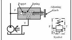
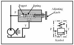
Figure 9-1 shows a cutaway view and the symbol for a direct-acting relief valve. The valve has a poppet that is pressed against its seat by an adjustable spring. An adjusting knob can be change the force on the spring to raise or lower maximum pressure. The poppet remains seated while pump flow goes to the circuit and pressure is lower than the relief valve setting. If pressure tries to go above spring setting, the poppet is forced off the seat just enough to pass excess pump flow to tank.
The symbol shows a single box with a flow arrow offset from the inlet P and outlet T flow lines. The dashed pilot line from the inlet line to the bottom of the box indicates inlet pressure can push against the flow arrow. On the opposite side of the box is a spring with a sloping arrow through it to show an opposing force on the flow arrow. When pressure at port P builds enough to overcome spring pressure, it forces the flow arrow up until there is a path from P to T. Although there is no pilot passage in the actual valve, the function is implied and thus is part of the symbol.
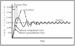
The main advantage of direct-acting relief valves over pilot operated relief valves is that they respond very rapidly to pressure buildup. Any relief valve does not know there is a problem until pressure is very near or at its setting. Then it must open to relieve excess flow as quickly as possible to keep pressure overshoot low. Because there is only one moving part in a direct-acting relief valve, it can open rapidly, thus minimizing pressure spikes. Figure 9-2 shows typical performance graphs from direct-acting and pilot-operated relief valves. Notice the difference in response time and pressure spikes as the valves open to send excess flow to tank.
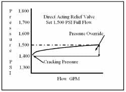
The main disadvantage of direct-acting relief valves is that they open partially at about 150 psi below set pressure. Because the poppet is in direct contact with the spring that sets maximum pressure, when the poppet opens it forces the spring back and increases pressure. The amount depends on the spring’s length and stiffness. The plot in Figure 9-3 shows the flow/pressure relationship of a typical direct-acting relief valve. With a direct-acting relief valve setting of 1500 psi at 10 gpm, it is very possible that some fluid will start to pass when pressure is as low as 1350 to 1400 psi. Continued pressure increase allows more flow until all pump flow goes to tank at 1500 psi. If work is still being performed at 1450 psi, it will be at a reduced speed because some flow is going to tank. When this valve is set at 1500-psi cracking pressure, no flow will bypass until pressure reaches that level, but final pressure would be as high as 1650 psi. (Pilot-operated relief valves . . . discussed next . . . do not start to open until pressure is within 25 to 50 psi of their settings.)
Direct-acting relief valves often are quite noisy due to the high velocity of the fluid bypass and the instability inherent in their design.
Direct-acting relief valves are not normally used on industrial hydraulic systems, except for those with flows under 3 gpm, and as pilot control devices. Most industrial designs use long springs that gain little force per compression increment to keep pressure override low.
When a direct-acting relief valve is specified as preset, non-adjustable, always specify whether the valve is to be set for cracking pressure or full flow. If full flow is desired, a flow must be specified also.
Pilot-operated relief valves
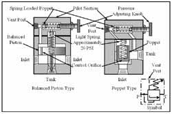
Figure 9-4 shows cutaway views of two common types of pilot-operated relief valves. There are many variations of these designs but the function and symbol are the same. The pilot section on each valve is a low-flow direct-acting relief valve that sets maximum system pressure. Because the valve is small and passes very little flow, it has less than 50-psi pressure override as it operates.
The control orifice in the balanced piston or poppet usually has a diameter around 0.040 in. This size gives good relief-flow stability and is not prone to becoming blocked with contamination. If the orifice is plugged, the balanced piston or poppet will open at approximately 20 psi and dump all pump flow to tank.
A flow path from the outlet of the control orifice . . . on top of the balanced piston or poppet . . . leads up to the pilot section, which contains a spring-loaded poppet. Adjusting the tension on the spring-loaded poppet sets the pressure in the circuit. Fluid used by the pilot section returns to tank through the tank port. The balanced-piston type has a hole through it that lets control fluid flow to tank. The vent port in the pilot section is normally plugged. (Removing the plug allows this valve to perform other functions.)
Many inline-mounted valves have two inlet ports as a piping convenience. Pump flow comes in one inlet and exits through the opposite one. This eliminates the need for a tee in the pump line plumbing.
How a pilot-operated relief valve works
Pump flow enters the inlet port and flows to the circuit and through the control orifice to the top side of the balanced piston or poppet. It also travels up to the pilot section’s spring-loaded poppet, where it is blocked. When pressure is too low to unseat the spring-loaded poppet, pressure is the same on either side of the balanced piston or poppet. Because hydraulic forces are equal on both sides of the balanced piston or poppet, the light spring holds them in their normally closed position. This condition continues until pressure reaches approximately 25 to 50 psi below the pressure set at the relief valve pressure-adjusting knob.
For example, if pressure was set at 1000 psi, at around 950 psi the spring-loaded poppet in the pilot section will crack open and allow a small amount of fluid to pass to tank. At this point the amount of fluid passing the spring-loaded poppet can easily flow through the control orifice so pump flow to tank is blocked. As pressure continues to increase, it finally forces the spring-loaded poppet in the pilot section to open far enough so that flow through it is greater than flow through the control orifice. When flow through the spring-loaded poppet is more than flow through the control orifice, pressure on top of the balanced piston or poppet decreases. When the pressure imbalance is great enough, the balanced piston or poppet moves toward the decreased pressure and opens a flow path to tank. Flow to tank is just enough to bypass any excess fluid the system is not using. As a relief function, this valve never opens more than enough to bypass excess flow.
When system pressure decreases, the spring-loaded poppet in the pilot section reseats. Fluid trapped on top of the balanced piston or poppet forces it to close and block pump flow to tank.
A pilot-operated relief valve allows all pump flow to go to the actuators almost to its final setting. This means the valve can operate at a lower maximum pressure and it will not slow actuator speed when forces increase.
Remote pilot operation
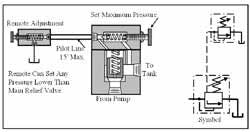
Another capability of pilot-operated relief valves is that they can be operated remotely. Figure 9-5 shows the vent port connected to a direct-acting relief valve at a remote location for easy pressure adjustment. Because a relief valve is normally mounted at or very near the pump outlet, it can be difficult to reach. When it is necessary to change pressures on a regular basis, the setup in Figure 9-5 works well. The vent port of the pilot-operated relief valve is connected to a direct-acting relief valve at a distance of 15 ft maximum. The pilot-operated relief valve is set for maximum pressure and the remote adjustment can set at any pressure lower than this maximum.
Using a 4-way directional control valve and three remote adjustments could allow electrical selection of three different pressures. Using more directional controls and more remote adjustments could give multiple pressure selections electrically.
Solenoid-operated relief valves
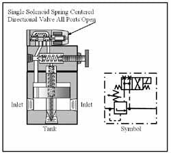
Figure 9-6 shows how a directional control valve attached to the pilot section and piped to the vent port and tank can bypass or block flow from the control orifice. Bypassing the control-orifice fluid allows pump flow to unload to tank at about 20 psi. Blocking control-orifice flow forces fluid to the circuit at pressures up to relief valve setting. This is one way to keep a fixed-volume pump from overheating the fluid when it is not performing work. (See Chapter 8, Figure 8-11 for a circuit that uses a normally open solenoid-operated relief valve to unload a fixed-volume pump in a multiple cylinder circuit.)
Solenoid-operated relief valves can be purchased in normally open mode (as shown), normally closed mode, and double-solenoid dual- or tri-pressure setups. (See Chapter 4 for symbols.) A solenoid-operated relief valve also can be used as a 2-way normally open or normally closed directional valve in high-flow circuits.
Proportional-solenoid relief valves
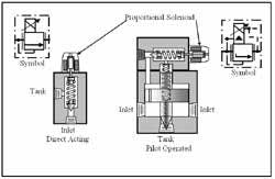
The relief valves in Figure 9-7 are electronically adjusted by using a proportional solenoid instead of an adjusting knob. A proportional solenoid produces increased force with increased voltage. These solenoids usually operate at 0 to.10 V on DC current. They can produce infinitely variable force. The direct-acting type is for low (below 3 gpm) flow. It also can serve in the pilot section of high-flow pilot-operated valves. Operation of a proportional relief valve is the same as for manually controlled valves. The difference is how the force on the control poppet is generated.
Unloading valves
Unloading valves are pressure-control devices that are used to dump excess fluid to tank at little or no pressure. A common application is in hi-lo pump circuits where two pumps move an actuator at high speed and low pressure, the circuit then shifts to a single pump providing high pressure to perform work.
Another application is sending excess flow from the cap end of an oversize-rod cylinder to tank as the cylinder retracts. This makes it possible to use a smaller, less-expensive directional control valve, while keeping pressure drop low.
Direct-acting unloading valves
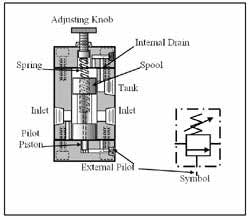
The cutaway view in Figure 9-8 shows the construction of a direct-acting unloading valve. The valve consists of a spool held in the closed position by a spring. The spool blocks flow from the inlet to the tank port under normal conditions. When high-pressure fluid from the pump enters at the external-pilot port, it exerts force against the pilot piston. (The small-diameter pilot piston allows the use of a long, low-force spring.) When system pressure increases to the spring setting, fluid bypasses to tank (as a relief valve would function). When pressure goes above the spring setting, the spool opens fully to dump excess fluid to tank at little or no pressure. (The example circuit in Figure 9-10 illustrates this function.)
Pilot-operated unloading valve
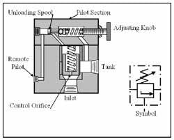
The cutaway view in Figure 9-9 shows a pilot-operated unloading valve. A pilot-operated unloading valve has less pressure override than its direct-acting counterpart, so it will not dump part of the flow prematurely. It also will go from no flow to maximum flow quickly, thus using all the flow from the high-volume pump flow for a longer period, and rapidly dropping horsepower draw from the high-volume pump.
(This valve design is also used as an unloading relief valve in accumulator circuits. Chapter 16 on Accumulators will have a circuit using this valve.)
A pilot-operated unloading relief valve is the same as a pilot-operated relief valve with the addition of an unloading spool. Without the unloading spool, this valve would function just like any pilot-operated relief valve. Pressure buildup in the pilot section would open some flow to tank and unbalance the poppet, allowing it to open and relieve excess pump flow.
In a pilot-operated unloading valve, the unloading spool receives a signal through the remote-pilot port when pressure in the working circuit goes above its setting. At the same time, pressure on the spring-loaded ball in the pilot section starts to open it. Pressure drop on the front side of the unloading spool lowers back force and pilot pressure from the high-pressure circuit forces the spring-loaded ball completely off its seat. Now there is more flow going to tank than the control orifice can keep up with. The main poppet opens at approximately 20 psi. Now, all high-volume pump flow can go to tank at little or no pressure drop and all horsepower can go to the low volume pump to do the work. When pressure falls approximately 15% below the pressure set in the pilot section, the spring-loaded ball closes and pushes the unloading spool back for the next cycle.
An unloading valve requires no electric signals. This eliminates the need for extra persons when troubleshooting. These valves are very reliable and seldom require maintenance, adjustment or replacement.
High-low pump circuit
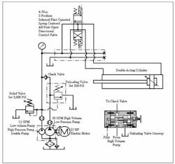
Often a cylinder needs very little force to stroke to and from the work -- and only a short high-force stroke to perform the work. When this is the case, the hi-lo circuit in Figure 9-10 works well and costs less.
For example: if a single-pump circuit needs 60 gpm to make the required cycle time and 3000 psi to perform the operation, the circuit would require a 110-hp electric motor to drive it (60 × 3000 × 0.000583 = 105 hp).
The circuit in Figure 9-10 is a typical hi-lo pump circuit that consumes less horsepower while maintaining fast cycle times. It uses a 25-hp motor and supporting equipment for less expense up front, as well as during its useful life. The motor drives a 50-gpm low-pressure pump and a 15-gpm high-pressure pump — for a total of 65 gpm. The extra flow is required to maintain cycle time because the work stroke is slower. The tank, valves, and line sizes are still rated for 65-gpm flow and 3000 psi, but the electric motor and controls are much smaller.
As shown in Figure 9-10, the hi-lo circuit also has a relief valve, an unloading valve, and a check valve. The relief valve protects the low-volume/high-pressure pump from pressure above 3000 psi. The unloading valve is set at 500 psi to divert flow from the high-volume/low-pressure pump to tank when system pressure climbs above this setting. A check valve after the high-volume/low-pressure pump isolates system pressure from the unloading valve circuit while performing work at maximum pressure.
A 4-way, 3-position, solenoid pilot-operated, spring-centered, all-ports-open directional control valve sends all pump flow to tank while the system is idle. This power unit and valve arrangement send a double-acting cylinder through a fast-approach, high-force work stroke and fast return – driven by a 25-hp electric motor. The unloading valve cutaway view shows the pipe connections to this in-line mounted valve.
Energizing solenoid A1 on the directional valve sends flow from both pumps to the cap end of the double-acting cylinder. The cylinder advances rapidly at low pressure until it contacts work. At this point, contact pressure builds quickly and when it passes 500 psi, the unloading valve is forced open. Now, all high-volume pump flow is diverted to tank at very low pressure (and horsepower). Up to this point, the highest horsepower draw would be: (65 gpm)×(500 psi)×(0.000583) = 19 hp.
With the high-volume pump unloaded, there is plenty of horsepower to raise the high-pressure pump to the 3000-psi pressure required to do the work. The work requires (15 gpm)×(3000 psi)×(0.000583) = 26 hp. This is well within the capability of the 25-hp motor specified.
A hi-lo circuit makes it possible to replace a high-horsepower motor and its control components with a much smaller less-expensive setup.
Other applications for relief valves
Relief valves are used in circuits to protect components from excess pressure due to heat or external forces where pressure buildup in a blocked flow circuit could damage an actuator or be a safety hazard.
In hydraulic motor circuits, relief valves can eliminate shock when the motor must be decelerated quickly. In this function, fluid is ported from the high-pressure outlet port of the motor to the low-pressure inlet port, while holding ample backpressure to stop the motor without damage.
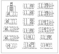
Most relief valve functions are available as modular or sandwich valves that mount between the directional control valve and sub-plate. Figure 9-11 shows most of the common configurations presently offered by fluid power suppliers. These modules are usually available in all valve sizes up to D08 (¾-in.) ports.
