This file type includes high resolution graphics and schematics when applicable.
Most reputable manufacturers consider safety to be vital on any factory floor. Recently, I examined sales of actuators and air-preparation products associated with safety. The goal was to determine which products were top sellers and, more importantly, to understand why these particular products were in high demand. Following discussions with distributors, OEMs, and our own internal team, we identified some relatively simple and low-cost components and systems that are essential for any pneumatic and hydraulic circuit—the workhorses of every system.
Upon reflection, I believe it is vital for OEM engineers to be acquainted with these products and to have them top-of-mind when designing a system. It is not an overstatement that these make up one’s essential safety “tool kit.” The first five products involve actuators, and the rest focus on air supply as it relates to safe equipment operation.
1. Pneumatic Actuator Clamping Units
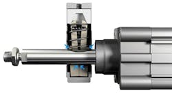
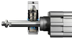
Cylinders with integrated clamps are needed on a machine when maintaining actuator position is essential to human and work-piece safety. A clamp keeps the actuator rod in a stationary vertical position and prevents it from retracting. Because these actuators are all about holding a position rather than stopping motion in an emergency situation, they are usually located in sections of a machine away from operators.
Clamping units are easy and inexpensive to integrate with pneumatic actuators, and they only require an air signal to operate. Compressed air maintains the spring-loaded clamp in the open position. Should there be a leak or an emergency evacuation of air, the spring snaps the clamp closed and holds the rod or guide rail in place until air pressure is restored.
2. Pneumatic Actuator Brakes
Clamps are ideally applied to a stationary rod or guide rail to maintain a position. Pneumatic brakes, on the other hand, are designed to stop a moving actuator regardless of position—and not damage the rod or guide during an emergency stop.
Brakes are used in areas where an operator may have routine access. Brakes are more expensive than clamps, and they require third-party certification. Similar to clamps, air pressure maintains the brake in an open positon. A spring snaps the brake closed when air is evacuated during an emergency stop or when air leaks out of the circuit.
3. Mechanical Locks
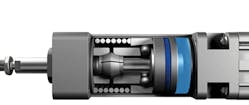
A mechanical lock automatically engages a locking pin each time the cylinder reaches its end point. This effectively holds the rod or guide in position. Positive air pressure is required to raise the locking pin and permit the actuator to retract.
Like clamps, mechanical locks are often applied in vertical holding applications. The locks ensure the rod or guide does not drop and potentially hurt maintenance personnel working on a machine or damage an expensive work piece. Mechanical locks are not used in areas where there is a high risk of injury because only the end position is controlled, not intermediate positions. The attractiveness of mechanical locks is their simplicity and holding strength. They are, however, more expensive than clamps.
4. Position Feedback: Mechanical Flag and Linear Potentiometer
In some applications, keeping track of piston position at all times is vital for safe operation. Typically, electric actuators use magnetic proximity sensors to signal position. A better, more reliable solution is to detect piston position using a metal flag and inductive sensor.
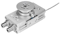
For example, in a rack-pinion rotary actuator, the flange and piston may not be in the same position should the gears break. It is safer to know the flange position. To accomplish this, a small metal flag attached to the flange indicates actual position. A linear potentiometer senses the flag position. A PLC can be programmed to shut down processes, remove pressure, and apply a brake or clamp if it indicates a fault position. The flag and linear potentiometer can be used with rotary as well as linear electric and pneumatic actuators.
5. Self-Adjusting Air-Cushion Cylinders
Most pneumatic cylinders have a needle-valve set screw that is used to adjust the cushioning up or down on a pneumatic cylinder and, consequently, the speed of the rod. Operators and maintenance personnel may tinker with the set screws to adjust the machine. The problem is that tinkering may take the machine out of specification.
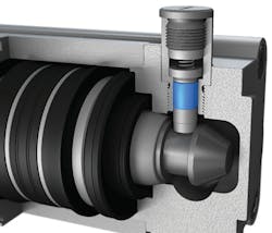
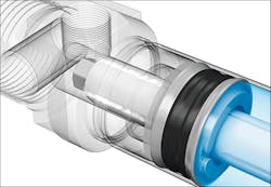
In contrast, a relatively new product eliminates the need for set screws. Festo has developed a self-adjusting pneumatic-cushioning system for its round-cylinder pneumatic actuators. The cushion relies on specially engineered air channels to vent the cushioning air, letting the cushions adapt their characteristics should cylinder loads and speeds change.
The cushion, designated PPS, provides dynamic but gentle damping as the load nears the end of the cylinder and eliminates the need to manually adjust end-position cushioning. The self-adjusting PPS cushions provide just the right damping even if parameters such as friction and pressure change. They also reduce acceleration forces on mating components and work pieces. This cuts down wear and minimizes shock and vibration. And because the exhaust flow from the cushioning chamber changes over the damping stroke, PPS cushions work with most commonly permissible speed and mass combinations, making them suitable for a wide range of applications.
Self-adjusting cushions also reduce machine setup and commissioning time, are tamper-proof, and should provide long, maintenance-free service life. Finally, the PPS system costs less than comparable manually adjustable cylinders.
In contrast to the previous discussion on actuators, the following sections note how air-supply products affect equipment safety.
6. Tamper-Proof Shut-Off Valves
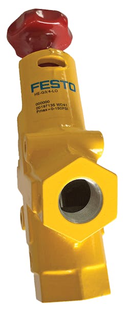
Tamper-proof “Lock Out Tag Out” (LOTO) valves manually shut off and vent pneumatic systems. These large and rugged LOTO valves are easily recognized because they’re bright yellow. While the tamper-proof valve may be used in emergency situations, it is mainly used during machine maintenance to ensure no active pressure is present.
Once pressure has been evacuated, maintenance personnel insert a lock or hasp in the valve, making it impossible to restore pressure while the lock is in place. Depending on pneumatic configurations, there may be several tamper-proof valves per machine. These valves are OSHA-compliant.
7. On-Off Valves with Piston Sensing
Unlike manually operated tamper-proof valves, a PLC electronically controls solenoid-actuated on-off valves with piston-position sensing. These units sense piston position and confirm the valve is either on or off. Other electronically controlled pneumatic on-off valves do not offer this feedback. Position sensing provides an extra margin of safety monitoring, and on-off valves can be integrated into a system to achieve a higher-category safety rating. Furthermore, these units mount directly to air-preparation modules for easier and more-straightforward installation.
8. Emergency Quick Exhaust
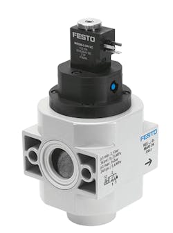
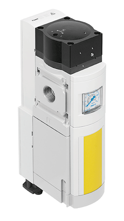
The emergency quick-exhaust system is the type of unit most people think of when they visualize a pneumatic safety product. When a penetrated light curtain or an open guard, gate, or door activates an emergency stop switch, these PLC controlled units exhaust air from the system at rates up to 9,000 liters/min—effectively removing pneumatic pressure. These systems should meet redundancy safety guidelines under ISO 13849-1.
These units should also protect against unexpected startups and provide for safe pressure buildup. At startup, a unit must receive two signals offset by milliseconds from the PLC. Offsetting the signals prevents startup due to a short circuit. Once the unit receives the two enable signals, it slowly lets pressure build in the system so that actuators safely complete the cycle that was interrupted by an emergency shut off.
The optimum unit in the “tool kit” should come standard with built-in diagnostics, freeing the OEM from having to provide its own diagnostic system. These units are typically certified by a third party to meet Performance Level e/Category 4, which also saves the OEM considerable time and expense.
9. Piloted Check Valves
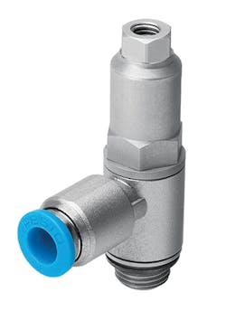
When air pressure is turned off, pneumatic pistons facing up may retract back into a cylinder and pistons facing down may fully extend. These movements may damage the machine, part, or people. A piloted check valve retains pressure in the cylinder, stopping it and holding it in place. Some models, for example, come standard with a manual override, which lets maintenance personnel evacuate air from the cylinder when it is judged safe to do so. Piloted check valves are useful for both emergency situations and for safety during maintenance.
10. Tamper-Proof Flow Controls
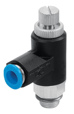
Flow-control valves are simple screwdriver-adjustable needle valves that control air flow. Technicians can open a valve for more flow and dial it down for less air. The potential problem with flow-control valves is that operators and maintenance personnel may tinker with valve settings for on-the-fly adjustments to air flow. A change in flow may appear to make a machine run faster or perform better, but it can damage parts by increasing wear and even causing unexpected safety problems.
Festo’s GRLA-SA economical exhaust air-flow control valves provide an ingenious solution—a spring pin protects against the unauthorized resetting of volumetric flow rate. It is as simple as that.
This file type includes high resolution graphics and schematics when applicable.
