Download this article in .PDF format
This file type includes high resolution graphics and schematics when applicable.
Concern for the environment has become a fact of life for most companies. For the companies that use hydraulic equipment, that concern is reinforced by stringent federal and local regulations requiring pollution prevention and governing disposal of used industrial fluids. Higher costs (and greater potential liabilities) for fluid disposal are a direct result of these regulations. This adds another economic item to the list of benefits derived from controlling contamination to extend the service life of hydraulic fluids. The list now includes:
• lower cost for fluid needed for replacement and replenishment
•more consistent hydraulic system performance
•less component wear, and
•reduced fluid disposal costs.
Contamination's detrimental effects
It is an established fact that particulate contamination and water in hydraulic fluids can have serious adverse effects on the fluids' physical and chemical properties. The loss of crucial fluid properties, which are central to useful service life, can result in inefficient system performance and accelerated mechanical and chemical wear processes.
Hydraulic fluids are carefully formulated for specific areas of application. They usually are comprised of a base stock and an additive package. The additive package consists of chemical compounds designed to protect the base stock — as well as the components in the hydraulic system — and to ensure proper performance of the system. Typical additives include dispersants and detergents; antioxidants; anti-corrosion, anti-wear, anti-foaming and extreme pressure (EP) agents; and viscosity-index improvers. Particulate contamination and water adversely affect both the base stock and the additives.
Water is a poor lubricant, and significant concentrations of water in hydraulic fluids can decrease their viscosity and load-carrying ability, as well as hydrodynamic-film thickness. This can lead to greater surface-to-surface contact at sliding and rolling dynamic clearances, and hence, increased component wear. The presence of free water in systems that could be exposed to temperatures below the freezing point of water can lead to icing, which will degrade system performance and can produce malfunctions.
The presence of both water and particulate contamination can lead to the formation of insoluble precipitates, and viscous sludges and gels. These materials induce excessive stress on system components — especially pumps — and can clog orifices, nozzles, and jets.
Degradation of fluid base stock
Dealing with acidic componentsPhosphate-ester fluids are particularly susceptible to hydrolysis during service, resulting in an accumulation of acidic hydrolysis products. A new trend in fluid purifiers is the incorporation of ion-exchange resin cartridges to remove acidic components from phosphate-ester fluids. If acidic components are a problem, these purifiers provide a double benefit: they remove water from the fluid to reduce the possibility of hydrolysis, and they adsorb any acidic hydrolysis products that already exist in the fluid to minimize acid buildup. |
Oxidation of the fluid base stock is a primary chemical-degradation process in many hydraulic fluids. The oxidation process proceeds through a series of chemical chain reactions and is self-propagating — with the intermediate, reactive chemical species regenerating themselves during the process. The result is the formation of oxygenated compounds (notably acidic compounds in the case of hydrocarbon, polyolester, or phosphateester base stocks) and, eventually, high-molecular-weight polymeric compounds. All of these compounds often are insoluble; they settle out of the fluid as gums, resins, or sludges.
Oxidation is significantly accelerated in the presence of metals and water. Metals act as catalysts, and fine metallic wear debris, commonly found in hydraulic systems, are especially active, due to their large effective surface area.
Table 1 summarizes data from tests that were carried out to quantify the effect of metal catalysts and water on oil oxidation. The tests were conducted on turbine-grade oil in a pure oxygen atmosphere, according to the ASTM/D-943 oxidation test procedure. The neutralization number, tabulated in the last column, is a measure of the extent of oxidation. The results show that the extent of oxidation is greatly increased: roughly 48-fold for iron/water and 65-fold for copper/water within 400 and 100 hours, respectively — compared to the baseline test with no water and metal catalysts. Even with only a single contaminant present (either water or a metallic catalyst), the neutralization numbers increase.
Table 1. Effect of metal catalysts and water on oil oxidation
CatalystWaterHoursFinalneutralization
number None No 3,500+ 0.17 None Yes 3,500+ 0.90 Iron No 3,500+ 0.65 Iron Yes 400 8.10 Copper No 3,000 0.89 Copper Yes 100 11.20
Hydrolysis — the alteration or decomposition of a chemical substance due to the presence of water — is another potential problem in hydraulic fluids. Fluid base stocks that are comprised of ester compounds, such as polyol esters and phosphate esters, can undergo hydrolysis under typical hydraulic system operating conditions. The acidic compounds that may form during hydrolysis can react with materials of the hydraulic-system components, leading to corrosion and insoluble corrosion products.
Additive depletion
Depletion of additives can occur either by their physical removal from the fluid or by chemical reactions which convert them to non-functional products. The solubility of many additives is critically dependent on fluid composition. The presence of water can lead to the precipitation of these additives from the fluid. In addition to being rendered non-functional, the precipitated additives contribute to the particulate contamination level in the fluid.
Additives that protect the base stock can be depleted rapidly due to the enhanced degradation of the base stock in the presence of both particulate contamination and water. A notable example is the depletion of antioxidants. A summary of the detrimental effects of particulate contamination and water is presented in Table 2.
Table 2: Effects of particulate contamination and water on hydraulic fluids
Fluid breakdownCauseEffect on system Physical properties a. Agglomeration and precipitation of particulate contaminationb. Oxidation/hydrolysis products - gums and sludges
c. Reactions involving additives - sludges and solids
d. Free water
- component wear
- clogging of jets, nozzles, and orifices; valve jamming
- system malfunction due to icing of free water
degradation a. Oxidation
b. Hydrolysis
- corrosion and surface degradation of components
b. Adsorption by particulates
c. Reactions involving additives
d. Abnormal degradation of base-stock
- loss of component protection
- increased component wear and corrosion
Monitoring contaminants
How can you check on the status of the hydraulic fluid in an active system? Not too long ago, you had to take samples of fluid from the system, send them to a laboratory, and wait for a report. Today, a variety of on-line monitors is available for in-house measurement of particulate levels and water concentration. Some monitors can be interfaced with fluid-purification devices for automated operation. When the monitor detects that preset threshold concentration limits for particulates and/or water have been reached, the contaminated fluid is directed into the purifier — with no operator intervention required.
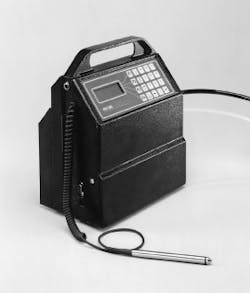
On-line particle counters or contamination monitors are used most commonly to measure particulate levels in fluids in installed systems. Particle counters provide an estimate of the particle size distribution, i.e., particle size vs number of particles, for several preset size ranges (usually six to seven). They operate on the principle of light obscuration by particles in the fluid-sample stream. Portable models, Figure 1, can be moved to multiple locations or installed at a single location for continuous on-line sampling. The contamination level typically is quantified in terms of the fluid cleanliness code (ISO 4406) or fluid cleanliness classes (NAS 1638 or ISO 11218).
Contamination monitors operate on the principle of mesh blockage by particles in the fluid-sample stream. They provide an estimate of the fluid cleanliness level in terms of cleanliness codes or cleanliness classes. Contamination monitors are the preferred choice for systems where the fluid properties prevent the use of light-obscuration particle counters: dark fluids that transmit light poorly or fluids containing air bubbles or emulsions.
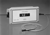
Typical on-line water monitors, Figure 2, are adaptations of devices that measure relative humidity. They indicate the percent saturation of water in the fluid — free water is 100% saturation — and the temperature. Note that the saturation level for water in hydraulic fluids depends on the specific fluid composition (both base stock and additive package), the actual condition of the fluid, and its temperature. The same type fluid, formulated by different manufacturers, could differ in water saturation levels. Likewise, the saturation level of the same fluid could differ over a period of time. Thus, correlation of the absolute water concentration, i.e., ppm concentration, with percent saturation, requires determination of the absolute water concentration in the specific fluid in question. In view of the above, it is most convenient to specify water concentration limits in terms of percent saturation.
Removal of water and particulate
Several methods also are available to remove particulate contamination and water from hydraulic fluids. The choice of method depends both on the contamination level of the fluid and its specific area of application. Heavily contaminated fluids are best cleaned by removing them from the operating system and purifying them externally prior to re-use. Subsequently, in-line particulate filters and water-absorbing filters can provide contamination control.
Although a variety of equipment is available to remove free water (e.g. centrifuges, coalescers, and water-removal cartridges), only fluid purifiers offer the ability to remove free, emulsified, and dissolved water. In addition to removing water and particulate contamination, fluid purifiers also take out volatile solvents and dissolved gases.
Two common types of purification devices are flash-distillation and vacuum-dehydration systems. In flash-distillation systems, fluid is heated and then introduced into a vacuum chamber so that free and dissolved water, gases, and solvents are distilled off, thus dehydrating the fluid. In vacuum-dehydration systems, the fluid is exposed to a low-humidity atmosphere in a partial vacuum chamber, resulting in the transfer of free and dissolved water, solvents, and gases from the fluid to the atmosphere in the vacuum chamber. To facilitate the transfer, the surface area of the fluid should be maximized.
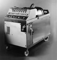
In one purifier design, Figure 3, the contaminated fluid is introduced into the vacuum chamber through fine spray nozzles to form a conical, thin film through which a flow of low-humidity air is directed. This arrangement results in a large fluid-surface area that allows for more efficient transfer of water from the fluid film to the air stream. The air then is exhausted through a de-mister filter to remove any residual fluid it may be carrying.
In the final stage of the purifier, de-aerated and dehydrated fluid exits the vacuum chamber through a particulate contamination-control filter. These fine filters have high efficiency particle-removal characteristics, especially in the smaller size ranges. For example, their particle-removal efficiency is 99.5% or higher for particles greater than 3 ∝m in size, i.e., β3 >200. These filters also exhibit a high dirt-retention capacity.
At work in the real worldOne U.S. airline studied the impact of contamination on performance in the hydraulic systems of its aircraft ground-support equipment, such as mobile cargo loaders, container rotators, aircraft bridges, and nose docks. This equipment operates outdoors and is exposed to dirt and weather extremes. Initial investigations revealed high particulate levels - 20/16 on the ISO 4406 scale - and water contamination in excess of 1,000 ppm. These conditions required fluid changes every two to three months. In spite of these relatively frequent changes, equipment failure was common. The airline initiated a comprehensive program of contamination control. It included installing high-efficiency fine filtration and the use of portable fluid purifiers. The result: hydraulic-fluid service life was extended to more than eleven months. The water concentration in the fluid was held consistently below the manufacturer's recommended 200- to 400-ppm level. Particulate levels were reduced to 13/11 on the ISO 4406 scale. The associated benefits were improved performance and less downtime. |
For several decades, a product called Air Cleaner Fine Test Dust (ACFTD) served as the standard solid-particle contaminant for a number of purposes in the area of hydraulic contamination measurement and testing. The irregularly shaped ACFTD particles - ranging in size from roughly 0 to100 mm - were very similar to the contaminants found in typical hydraulic systems. In the particle-size distribution defined by ISO Standard 4402, ACFTD was used to set the electronic threshold levels that establish the particle sizes measured in automatic particle counters (APCs). The dust also was added to fluids in filter-performance testing to measure both the efficiency and dirt-holding capacity of filter media. In addition, ACFTD was used to test the contaminant sensitivity of hydraulic components.
The AC Spark Plug Div. (later the AC Rochester Div.) of General Motors Corp. manufactured ACFTD by collecting dust - primarily silica - from a certain area in Arizona, then ball milling and classifying it into a consistent particle-size distribution. But in 1992, GM announced that it would discontinue production of ACFTD.
As a result, ISO Technical Committee TC 22 and the Society of Automotive Engineers (SAE) went to work to find suitable test dusts to replace the old standard. Their efforts produced a new standard, ISO 12103-1, 1997, which defines and designates four new test dusts. Powder Technology, Inc. (PTI), Burnsville, Minn., manufactures these dusts from the same silica-based material used by AC Rochester so that their chemical characteristics are similar to the AC Test Dusts. In a slightly different production method, PTI processes the Arizona dust with a jet mill and then classifies it. Of the four new dusts, ISO Medium Test Dust (ISO MTD) has a particle-size distribution closest to ACFTD and, therefore, has been selected as the replacement dust for APC calibration and filter-testing purposes.
While it is very similar to ACFTD, ISO MTD produces test results that are somewhat different. Therefore, results of both automatic particle counting and laboratory filter performance testing (including filter efficiency and dirt-holding capacity) can be significantly affected. Note that this is an artifact of the testing only; filter performance and actual contamination levels in the field will remain the same as before.
NIST certification and new calibration
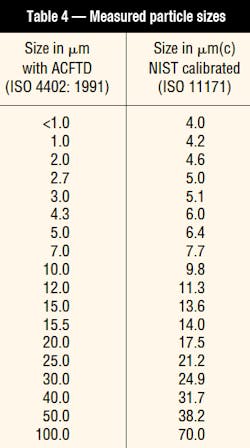
The US National Institute of Standards and Technology (NIST) undertook a project to certify the particle-size distribution of ISO MTD suspensions in oil. From this study, the Institute determined that for particle sizes below 10 µm, the actual particle size is greater than previously measured using an automatic particle counter that was calibrated with ACFTD. Above 10 mm, the particles were smaller than under the old calibration system. To make a distinction, particle sizes based on the new NIST determination will be represented as X µm(c), with the (c) designation referring to certified calibration that has sizes traceable to NIST. Thus, particle size has a new definition, Table 4.
ISO Technical Committee TC 131 replaced the old APC-calibration procedure, ISO 4402, with a new procedure, ISO 11171, which incorporates ISO MTD test dust with the NIST particle-size and particle-count determinations. It also has included a number of other enhancements to ensure better accuracy, reproducibility, and repeatability. In addition, ISO has developed another procedure, ISO 11943, for calibration and verification of on-line automatic particle counters. Because APCs are used for multi-pass filter performance testing and fluid contamination measurement, these changes will affect reported results.
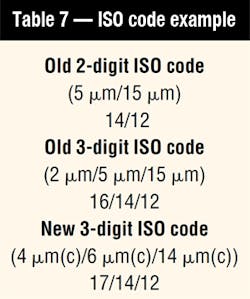
ISO has adopted a revised procedure for reporting fluid-cleanliness measurements from APCs that have been calibrated with the new NIST-traceable method. This procedure, ISO 4406: 1999, uses three code numbers that correspond to concentrations of particles larger than 4, 6, and 14 µm(c). The new 6 and 14 µm(c) sizes correspond closely to the older 5 and 15 µm sizes reported by the old ISO 4406 coding system measured with an APC calibrated with ACFTD. The new 4 µm(c) size, however, corresponds to about the 1 µm size if the ACFTD calibration procedure had been used. This difference results in somewhat higher values of the first digit when compared to current three-digit codes that reference particles larger than 2 µm using the old ACFTD-calibration method.
Filter performance testing
A number of substantial changes were made to ISO 4572, the multi-pass filter test procedure. These changes again were intended to produce more repeatable and reproducible test results. The new method, ISO 16889 replaces ISO 4572, and incorporates ISO MTD and the NIST-traceable APC-calibration procedure. Beta ratios derived from tests that use this new ISO procedure also are designated with the symbol (c) to signify they were measured in accordance with the ISO 16889 procedure using NIST-traceable calibration. As an example, a beta ratio of 200 at 5 µm(c) would be designated as β5(c) = 200.
We performed tests on Pall Industrial Hydraulics standard filter media using the new ISO 16889 test method. Comparisons to results obtained from the previous ISO 4572 method are shown in Table 5. Note that filter performance in the field does not change at all. The media are no more or less efficient at removing harmful particles. Only the reported laboratory results have changed slightly because of the new procedures and methods.
Filter dirt-holding capacity
The replacement of ACFTD with ISO MTD in the multi-pass test also affects retained-dirt-capacity values for filter elements. Capacity may be somewhat higher or lower with the new dust, again depending on the specific filter being tested. However, most filters we evaluated exhibited an increase of about 10% to 40% in dirt-holding capacity when using ISO MTD. Because each type of filter performs differently with the new dust, there is no single conversion factor to change ACFTD capacities into ISO MTD capacities.
Again note that an increase or decrease in dirt capacity when tested with ISO MTD does not imply that the filter's actual service life will be longer or shorter. In fact, there will be no change in field-service life. As a rule, dirt-holding capacity should not be used as an indicator of field-service life.
Reporting fluid cleanliness
The changes discussed in the previous sections will not affect the actual cleanliness of fluids in the field. However, for those technicians reporting data using particle counts, the changes in APC calibration will affect results obtained from both laboratory and portable equipment that is calibrated to the new standards, as in Table 6.
Conclusion
This will undoubtedly cause some confusion, but remember that any impact is merely an artifact of the minor changes in testing. Actual filter performance and field fluid contamination levels will remain the same.
This file type includes high resolution graphics and schematics when applicable.


